


LCX9000 Liquid-Cooled Drives User Manual
MN04005001E
For more information visit: www.EatonElectrical.com 1-5
January 2007
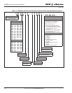
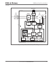
Figure 1-1: Liquid-Cooled Drive Principal Block Diagram
Control
I/O
Motor and
Application
Control
Control Keypad
Control Module
PE
Power Module
RS-232
Control
I/O
Measurements
Motor
Control
ASIC
Gate
Drivers
Power
Supply
Charg. Res.
Control
I/O
Control
I/O
Control
I/O
Brake *
Chopper
Brake Resistor *
3~
U
V
W
=
=
3~
Mains
External
Choke
L1
L2
L3
Motor
IGBT
Inverter
Rectifier
(Frequency
Converters Only)
Current
Sensors
* Brake resistor is available as optional equipment for all sizes (CH3 to CH7).
An internal brake chopper is standard equipment in CH3 only, while in all other sizes it is optional
and installed externally.
(1)
(2)
(3)