


LCX9000 Liquid-Cooled Drives User Manual
4-18 For more information visit: www.EatonElectrical.com
MN04005001E
January 2007
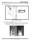
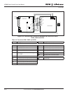
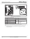
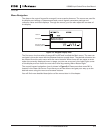
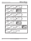
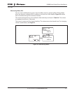
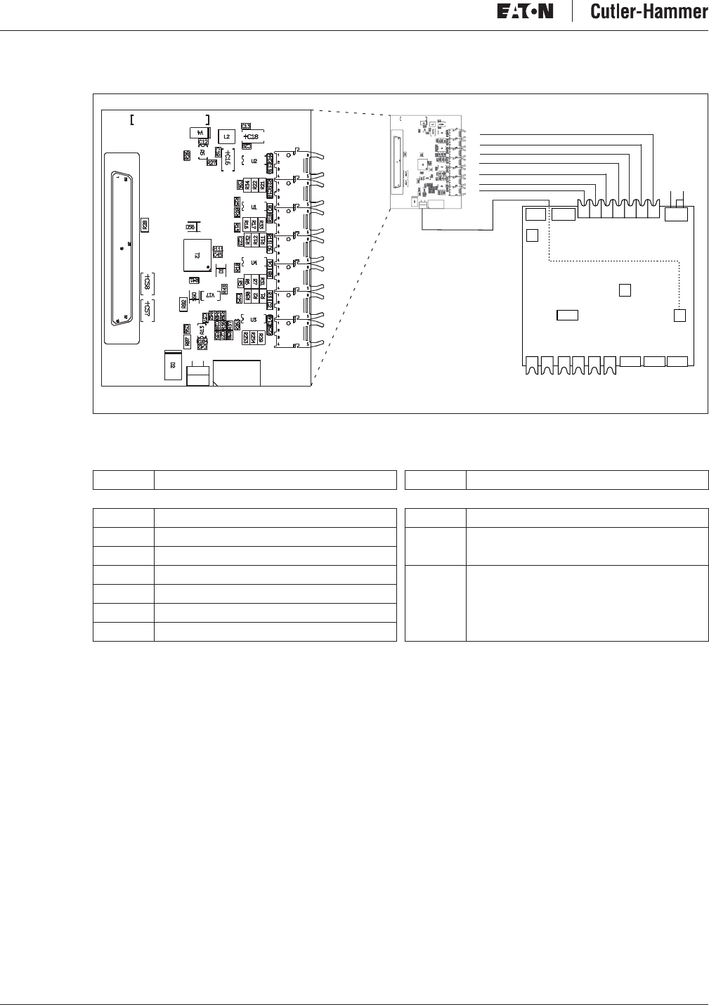
Figure 4-19: Optical Cable Adapter Board
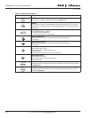
Table 4-6: Terminals on Adapter Board
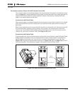
Note: The minimum optical cable bending radius is 1.97 inches (50 mm).
Note: Terminals X2 and X3 can be in use simultaneously. However, if the +24V supply from
the control I/O terminals (e.g. from board OPT-A1) is used, this terminal must be
protected with a diode.
Terminal Description Terminal Description
Optical Terminals on Optical Cable Adapter Board Other Terminals on Adapter Board
H1 Gate control enable X1 Control board connection
H2 Phase U control X2 Supply voltage 24V
in
(from power unit
ASIC)
H3 Phase V control
H4 Phase W control X3 Supply voltage 24Vin (customer);
●
Max. current 1A
●
Terminal #1: +
●
Terminal #2: -
H5 ADC synchronization
H6 Bus data from control board to ASIC
H7 Bus data from ASIC to control board
X9 X15
X29
H1 H2H3 H4H5 H6H7
X6
DC- DC+
ASIC Board
X26
X1
X10
UH VH WH
UL VL WL X3 X4 X5
H1
H2
H3
H4
H5
H6
H7
X1
X2 X3
H7
H6
H5
H4
H3
H2
H1
X1
X2 X3