


LCX9000 Liquid-Cooled Drives User Manual
4-2 For more information visit: www.EatonElectrical.com
MN04005001E
January 2007
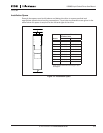
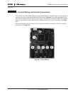
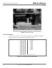
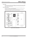
Figure 4-2: Basic and Option Board Connections of the Control Board
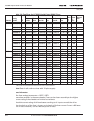
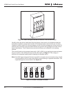
Usually, when the drive is delivered from the factory, the control unit includes at least the
standard compilation of two basic boards (I/O board and relay board) which are normally
installed in slots A and B. On the next pages you will find the arrangement of the control I/O
and the relay terminals of the two basic boards, the general wiring diagram and the control
signal descriptions. The I/O boards mounted at the factory are indicated in the catalog
number.
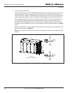
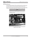
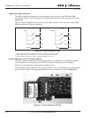
The control board can be powered externally (+24V, ±10%) by connecting the external power
source to either of the bidirectional terminals, #6 or #12, see Page 4-7. This voltage is
sufficient for parameter setting and for keeping the fieldbus active.
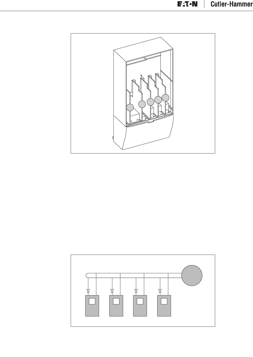
Note: If the 24V inputs of several drives are parallel connected, we recommend using a diode
in terminal #6 (or #12) in order to avoid the current flowing in opposite directions. This
might damage the control board. See Figure 4-3.
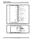
Figure 4-3: Drives Connected in Parallel
D
C
B
A
E
#
6
External
+
24V
+
–
#
7
#
6
+
–
#
7
#
6
+
–
#
7
#
6
+
–
#
7