


© 2006 Maytag Services 16026923 25
To avoid risk of electrical shock, personal injury or
death; disconnect power and gas before servicing,
unless testing requires power and/or gas.
Disassembly Procedures
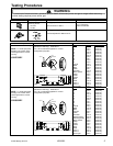
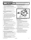
Burner Switch Replacement
1. Remove control panel, see "Control Panel Assembly
Removal" procedure.
2. Disengage burner switch from burner valve and
remove switch from valve.
3. Reverse procedure to reinstall burner switch.
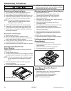
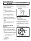
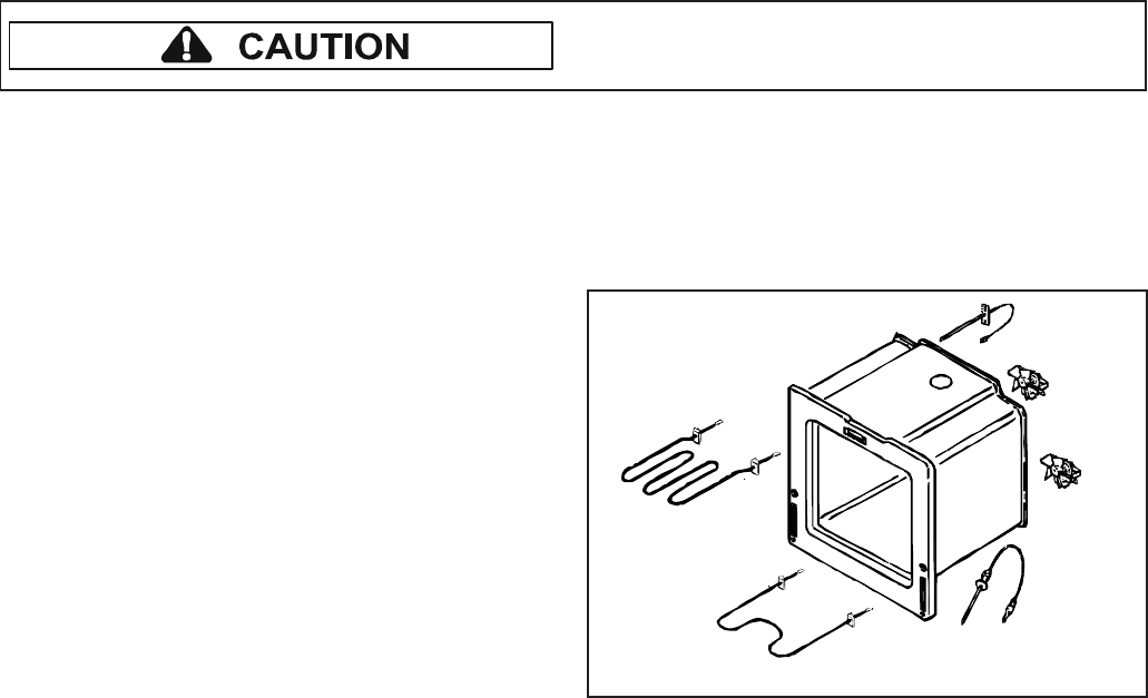
Oven Sensor
Meat
Probe
Broil Element
Bake
Element
Cooling
Fan
Convection
Fan
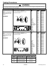
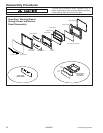
Meat Probe Receptacle Replacement
(Select Models)
1. Remove power from unit.
2. Remove range from installation position, see
“Removing and Replacing Range” procedure.
3. Remove front side trim, see "Front Side Trim
Removal" procedure.
4. Remove screws securing side panel to chassis and
main top.
5. Open oven door and remove nut securing meat probe
receptacle to oven cavity.
6. Label and disconnect wire terminals from receptacle.
7. Gently slide meat probe receptacle through oven
cavity.
8. Reverse procedure to reinstall meat probe receptacle.
Back Panel Removal
1. Remove power from unit.
2. Remove range from installation position, see
“Removing and Replacing Range” procedure.
3. Remove screws securing back panel to unit.
4. Slide back panel up and out to remove.
5. Reverse procedure to reinstall back panel.
Spark Module Replacement
1. Remove unit from installation position, see
“Removing and Replacing Range” procedure.
2. Remove screws securing rear access panel.
3. Disconnect and label wire connections from the spark
module.
4. Remove screws securing spark module to unit
chassis.
5. Replace and reverse procedure to reassemble.
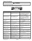
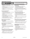
Manifold Assembly Removal
1. Remove maintop, see "Maintop Assembly Removal"
procedure.
NOTE: If replacing manifold only, skip step 2.
2. Loosen and disconnect fittings securing surface
burner tubing to burner assembly and manifold.
3. Remove bolt(s) securing surface valve(s) to manifold.
4. Remove bolt securing shut-off valve from manifold.
5. Disconnect tubing from manifold to the regulator.
6. Reverse procedures to reassemble.
NOTE: Perform gas leak test.
Control Panel Assembly Removal
1. Remove power from unit.
2. Remove burner switch control knobs.
3. Remove front screws securing control panel to
chassis.
4. Remove screws located on the left and right sides of
the control panel.
5. Grasp control panel on the far left and right sides and
gently pull the control panel out and down.
NOTE: The electronic control located in the control
panel is a sensitive item, handle gently.
6. Label and disconnect wire terminals.
7. Remove infinite switch control knobs, infinite
switches, indicator lights, rocker switches, and
electronic control/clock (as necessary) and transfer to
the new control panel.
8. Reverse procedure to reinstall control panel.
Electronic Control Replacement
1. Remove control panel, see “Control Panel Assembly
Replacement” procedure, steps 1 through 5.
2. Remove screws securing electronic control bracket to
control panel.
3. Label and disconnect terminal wiring from electronic
control.
4. Slide electronic control down and out of bracket,
applying slight outward pressure to the inside edges
of the electronic control bracket.
5. Reverse procedure to reinstall electronic control.