


CLEANING
Proper care should be taken to fully clean the griddle
on a regular basis.
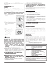
A. CONTROL PANEL – Clean any grease build-up on
switches and thermostat knobs.
IF ELECTRONIC IGNITION MODEL:
DISCONNECT ELECTRIC POWER SOURCE
BEFORE CLEANING. (REFER TO ELECTRONIC
IGNITION MANUAL)
NOTE: If grease gets into the working mechanism of a
switch or thermostat, it may cause the unit to fail.
B. CABINET - The front, back and sides of the cabinet
should be kept clean for sanitary reasons.
GREASE BUILD-UP NEAR ANY OPEN FLAME IS A
FIRE HAZARD.
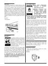
C. FLUE - The flue has been designed specifically to
exhaust the by-product of any combustion. Any
objects (steak weights, egg covers, pans, rags,
utensils, etc.) placed on the flue will inhibit the proper
combustion and exhaust, therefore causing health
hazards.
LIMITED
CALIBRATION
NOTE: Calibration is not covered under warranty.
Tools: Accurate surface thermometer
Standard screwdriver
Calibrating screwdriver
1. Turn the exhaust system ON.
2. Turn on the griddle with thermostat set at 300°F.
Turn switches to ON positoin to allow burners to
cycle on and off three times. (Approximately 60
minutes.)
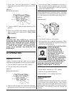
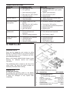
3. Place thermometer on surface over thermostat bulb.
Use the inverted “V” to locate thermostat bulb. See
Figure 3-3. When you have located the inverted “V”,
the thermostat bulb is approximately 2/3 to 3/4 of the
way straight back to the rear of the griddle.
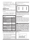
4. When burners cycle off, griddle is up to temperature.
If temperature is within 25°F of thermostat setting,
loosen the four retaining screws on the dial plate.
Rotate the dial plate. Indicating arrow on the
thermostat knob should point to the temperature
indicated on the thermometer.
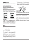
Piezo Spark Ignitor
“ON/OFF” Switch
5. Tighten screws.
For calibration over a 25°F difference, contact your
local service agent.
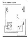
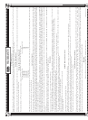
V SERVICE DIAGNOSIS
The following diagnosis is only to be used as a guide to
qualified service personnel. Keating recommends that
you use a qualified service company. (Equipment still
under warranty requires it.)
NOTE: To correctly and quickly diagnose the system,
the following chart should be followed in sequential
order.
7