


3
LEVELING
The griddle will operate at its highest efficiency when
properly leveled. Place a level on the griddle plate from
side to side. For griddles on legs, the bottom foot of the
leg is adjustable. Turn counterclockwise to decrease
height or clockwise to increase height until level. For
griddles on stands with casters, the casters are
adjustable by loosening the jam nut and turning the
caster in or out. When the desired level is reached,
tighten the jam nut. Adjustments of more than 3/4" are
not recommended on any caster. The same procedure
should be followed to level the griddle from front to
back.
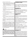
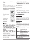
Figure 2-1
Leveling Griddle
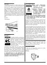
RESTRAINING
DEVICES
On griddle installation on stands with
casters, jam nuts must be completely
tightened. Adequate means must
also be provided to limit the
movement of the appliance without
depending on the connector, the
quick-disconnect device or its
associated piping to limit the
appliance movement.
Connectors must comply with the current ANSI
Z21.69/CAN 1 CAN/CGA 6.16 (latest edition) standard
for connectors for movable gas appliances. Quick-
disconnect devices must comply with the ANSI
Z21.41/CAN 1 6.9 (latest edition) standard for quick-
disconnect devices for use with gas fuel as applicable.
IF DISCONNECTION OF THE RESTRAINT IS
NECESSARY, IT MUST BE RECONNECTED WHEN
THE MIRACLEAN® GRIDDLE IS RETURNED TO ITS
ORIGINALLY INSTALLED POSITION.
GAS CONNECTION
PIPE JOINT COMPOUNDS
RESISTANT TO PROPANE
GASES MUST BE USED.
BEFORE OPERATING THIS
GRIDDLE, CHECK PIPE
JOINTS FOR LEAKS BY USING
A SOAP AND WATER
SOLUTION ONLY. DO NOT USE
AN OPEN FLAME!
DO NOT SHORT GAS VALVE TERMINALS WHEN
TESTING WIRING, AS THERMOSTAT AND GAS
VALVE DAMAGE MAY OCCUR AND CAUSE
UNSAFE CONDITIONS.
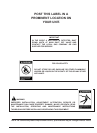
You will post, in a prominent location, instructions to be
followed in the event the user smells gas. This
information shall be obtained from your local gas
supplier. You may use the yellow stick-on label
enclosed on page “ii” temporarily until you receive the
data from your local gas supplier.
Connect the griddle to the main gas supply line at the
rear of the griddle. The piping should be a minimum of
3/4" IPS supply pipe for a single griddle at the burner
manifold. Installation must conform to the current local
and NATIONAL FUEL GAS CODE ANSI Z223.1 /
NFPA 54 (latest edition), Natural Gas Installation Code
CAN/CGA-B149.1 or Propane Installation Code
CAN/CGA-B149.2 (latest edition).
A 3/4" NPT manual gas valve is shipped with each
griddle for field installation. The required gas pressure
for proper operation of each griddle is 4" water column
for natural gas and 10” water column for Propane gas
at the burner manifold.
NOTE: If more than one gas unit is on the same supply
line, you may require a larger line. Consult your local
gas company to assure adequate volume and
pressure. Refer to serial plate for proper gas
requirements for your particular model.
GAS LEAK TESTING
1. Make sure all thermostats, switches and safety
valves are in the “OFF” position.
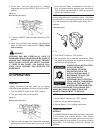
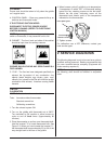
Figure 2-2
Thermostat
Restraining
devices required.