


B3000 SERVICE MANUAL
60-200807-000, REV C 6
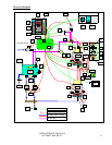
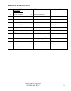
B3000 Brewer Water Flow Mechanisms
A schematic and legend showing the major components of the B3000 are provided (refer to page 8 and
9). The functions of these components are listed below.
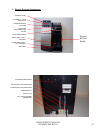
1. Water filling – The B3000 is a direct plumbed machine. Municipal water is introduced to the unit
through the inlet valve [X]. The supply water is then led to the cold water tank [BB] via the rigid plastic
tube connected to the float valve [Y]. The cold water tank is allowed to fill approximately 16 ounces,
(480 milliliters) and then the valve [X] is de-energized (closed) by the CWT float magnet proximity
switch [Z] which controls the fill level. The proximity switch (located outside the tank) contains
magnetically activated reed switch which is controlled by a float magnet (located inside the tank) that
monitors the water level.
2. The Cold water Tank – The cold water tank [BB] functions primarily as housing for the secondary
overfill protection device which is the float valve [Y] and provides the air gap necessary for back flow
protection. If the normally closed inlet valve [X] were to fail open or otherwise be prevented from
closing due to debris or CWT float magnet / switch failure, then the float valve [Y] would shut off the
water supply once the water level rose to the level to activate the float lever. Back flow is prevented as
the float valve inlet is approximately 1 1/4 inches (29 mm) above the over flow port in the cold water
tank [BB]. The cold water tank also functions as the water supply reservoir for the brewing system.
The water supply in the tank is fed through two check valve [M] and tubing to the two cold water pumps
(CWP) [W] that supply water to the hot water tanks via the CWP elbow, CWP connectors, silicone
tubing, multi-connector tee, and silicone tube.
3. The Hot Water Tanks – The water flows through the bottom tank and into the top tank via a seal
assembly which includes two o-rings, a seal washer (between the o-rings), and the sealing cover. To
allow the hot water tanks to fill, the vent valve [J] is energized (opened) to allow air to leave the system
as the tanks are filled with water. Water delivered to the hot water tanks [TP] and [TB] is heated by the
heating elements located inside the tanks. The only one heater at a time is allowed to energize and the
heater in the top tank (brew tank) has priority. The water temperature is controlled by the thermistors
[V] located in each tank. To control volume stainless steel conductive probes are used to sense the brew
volumes of 4, 6, 8, and 10 ounces (120, 180, 240, and 300 milliliters). In order to brew the system is
closed, vent valve [J] de-energized (closed) to allow pressurization.
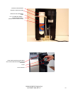
4. The Puncture Mechanism – the mechanism [DD] consists of the K-cup holding and puncturing
apparatus, a hot water delivery and brewed coffee path, and the hot water dispense valve [OO]. To brew
coffee one lifts the handle to present the K-cup holder [AA]. A K-cup is placed in the holder and the
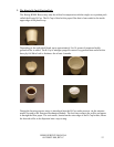
handle is returned to the closed position. Upon closing the mechanism, the K-cup is punctured on the
top first by the entrance needle [N] and then the bottom by the exit needle [P]. The holes created in the
K-cup by the two needles are sealed about the needles by gaskets. Once the K-cup is in this ‘ready to
brew’ state and a cup is placed on the drip tray, brewing can commence. To brew, the system is closed,
vent valve [J] de-energized and the brew pump [G] is energized. The brew pump pressurizes the system
to approximately 4 psi (27.6 kPa). The air is delivered to the top of the brew tank via a silicone tube by
way of the filter tee [H]. The water in the brew tank is forced out of the tank through the integral brew
tube [L] in the upper hot water tank cover. The water flows out of the top cover through a silicone tube
to the entrance elbow which contains a check valve [M]. The water flows next trough the entrance
needle, contacts the coffee grounds in the K-cup, and brewed coffee is delivered through the exit needle
to the cup located on the drip tray.