


30
Electrically bond boiler to ground in accordance with
requirements of authority having jurisdiction. Refer to:
• USA- National Electrical Code, ANSI/NFPA 70.
• Canada - Canadian Electrical Code, Part I, CSA C22.1:
Safety Standard for Electrical Installations.
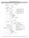
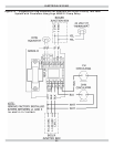
Electric Power Supply
Prior to making any line Voltage connections, turn OFf
electrical power at fuse box.
1.
Run separate 115 Volt circuit from separate over
current protection device in electrical service entrance
panel. This should be 15 ampere circuit.
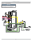
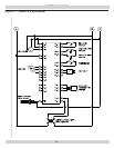
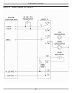
2.
See
Figure20, Page31 for diagram showing service
switch junction box and power supply connection
points.
3.
Locate service switch in vicinity of boiler. Verify it is
turned OFF during service or maintenance.
• Connect black (hot) lead from power supply to black
wire labeled L 120 VAC.
• Connect white (neutral) lead from power supply to
white wire labeled N 120 VAC.
• Connect green (ground) lead from power supply to
green wire labeled G 120 VAC.
4.
Run 14 gauge or heavier copper wire from boiler to
grounded connection in service panel or properly driven
and electrically grounded ground rod.
ELECTRICAL WIRING
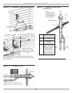
Thermostat Installation
• Thermostat location has important effect on operation
of boiler system.
• Follow instructions included with your thermostat.
• Locate thermostat about fi ve feet above fl oor on inside
wall.
• Mount directly on wall or on vertical mounted outlet
box.
• It should be sensing average room temperature.
Set heat anticipator (where applicable) at 0.7 amps.
Connect 24 Volt thermostat leads to two(2) yellow wires
located in junction box, located on outer jacket of boiler.
See Figure 20, Page 31 for junction box and thermostat
fi eld wiring connections.
Things to Avoid when Locating Thermostats
DEAD SPOTS:
Corners and alcoves Behind doors
COLD SPOTS: HOT SPOTS:
Concealed pipes or ducts
Concealed pipes
Fireplace
Stairwells - drafts
TV sets
Radios
Unheated rooms on
other side of wall
Lamps
Direct sunlight
Kitchens
Connect Circulator Pump Wiring
See Figure 20, Page 31 for circulator pump fi eld wiring con-
nections.
Supplied 5 foot wiring harness with fl exible metal conduit
for connection from circulator pump to junction box.
If two 120 Volt circulator wire terminals inside junction box
are not used, leave two wire nuts to prevent short circuit.
WARNING
Electrical shock hazard. Turn OFF electrical power
supply at service panel before making electrical
connections. Failure to do so could result in death
or serious injury.
!
NOTICE
Label all wires prior to disconnection when servicing
controls. Wiring errors can cause improper and
dangerous operation. Verify proper operation after
servicing.