


42
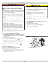
First couple of cold starts may be rough due to gas line not
being completely purged of air, causing low fi ring rate and
high excess air levels.
Inspect Venting And Air Intake System
Operate boiler and verify all vent/air intake connections are
gas-tight and watertight. Repair any leaks immediately.
Inspect Condensate Drain
Verify all connections are watertight, and that condensate
fl ows freely. Repair any leaks immediately.
Inspect System Piping
Verify all connections are watertight. Repair any leaks
immediately.
Test Ignition System Safety Shutoff Device
1.
Turn off manual gas valve
2.
Set thermostat to call for heat
3.
Boiler begins normal sequence of operation
4.
After approximately 20 seconds (pre purge, state code
4) gas valve is powered (state code 6).
5.
After 13 second trial for ignition, gas valve closes,
(state code 10)as integrated boiler control senses that
fl ame is not present.
6.
After about 30 seconds, control will go back to step 4
and make two more attempts to light the burner, then
go into soft lockout and display Error code 62.
7.
To restart system, open manual gas valve that was
closed in Step 1. Reset lockout by breaking and
restoring power to boiler. Observe normal operation.
CHECK OUT PROCEDURE AND ADJUSTMENT
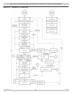
Verify Proper Sequence Of Operation
Place boiler into operation and observe operation through
several cycles. Follow remaining steps in this section to
insure boiler is operating correctly.
Test High Limit Control And Adjust
While burner is operating,adjust high limit setpoint below
actual boiler water temperature. Burner should go off while
circulator continues to operate. Raise limit setting above
boiler water temperature and burner should reignite after
inter-purge (retry delay). Set high limit control to design
temperature requirements of system. Maximum high limit
setting is 190°F. Minimum high limit setting is 80°F.
Test Other Safety Controls
If boiler is equipped with low water cut off, manual reset
high limit, or additional safety controls, test for operation
as outlined by control manufacturer. Burner should be
operating and should go off when controls are tested. When
safety controls are restored, burner should reignite.
Set Thermostat Heat Anticipator (If Used) And
Verify Thermostat Operation
For single thermostat connected to yellow thermostat lead
wires in furnished fi eld wiring junction box, heat anticipator
should be set at 0.7 amps. For other wiring confi gurations,
refer to instructions provided by thermostat manufacturer
regarding adjustment of heat anticipator. Cycle boiler
with thermostat. Raise thermostat to highest setting and
verify boiler goes through normal start up cycle. Lower
thermostat to lowest setting and verify boiler goes off.
Measure Natural Gas Input Rate
Correct input rate is essential for proper and effi cient
operation of the burner and boiler.
1.
Determine elevation at installation site.
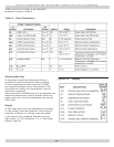
2.
Table 1 and Table 2, Page 6 to determine correct input
rate for the local elevation.
3.
Obtain yearly average heating value of local gas supply
from gas utility. At sea level elevation, it should be
approximately 1000 Btu’s per standard cubic foot.
4.
Operate boiler for 5 minutes.
5.
Turn off all other gas appliances, extinguishing standing
pilots where applicable.
6.
At gas meter, measure time in seconds required to use
one cubic foot of gas.
7.
Calculate input rate according to the following formula:
3600 x heating value from step 3
Btuh in put rate = time from step 6
8.
Measured input rate should be within +/-2% of input
rating from step 2. If within 2%, go to step 9. If not,
adjustment is required, proceed as follows:
A. Turn boiler off
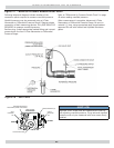
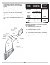
B. Set up U-tube manometer or differential pressure
gauge for measuring manifold pressure. See
Figure 27, Page 44 .
C. Manometer or gauge must be able to read at least
0.0 to 3.0 inches water column of pressure, and
resolve to at least 0.1 inches water column.
D. Turn boiler on.
E. Manifold pressure has been nominally set at 2.5
inches w.c. Manifold pressure and input rate must
always be measured with pressure regulator cover
screw installed. Cover screw must be removed for
adjustment. Manifold pressure reading will change
(increase) when cover screw is removed.