


44
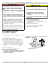
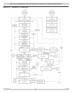
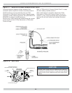
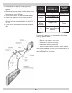
Following steps and diagram indicate location of the
connection points required to measure manifold pressure.
Manifold pressure may be measured using a U-Tube
Manometer or Differential Pressure Gauge. Diagram shows
connection of both measuring devices. Only ONE DEVICE IS
REQUIRED to measure manifold pressure.
Remove plug. Install appropriate barbed fi tting and connect
pressure side line from U-Tube Manometer or Differential
Pressure Gauge.
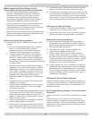
OFF
ON
INLET
OUTLET
GAS CONTROL KNOB
PRESSURE REGULATOR
ADJUSTMENT (UNDER CAP SCREW)
INLET
PRESSURE
TAP
VR8205
WIRING TERMINALS (2)
OUTLET
PRESSURE
TAP
Figure 27 - Manifold Pressure Measurement Detail
Figure 28 - Gas Valve
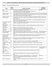
CHECK OUT PROCEDURE AND ADJUSTMENT
Refer to “Differential Air Pressure Switch Check” on page
49 when reading manifold pressure.
When measurement is complete, disconnect U-Tube
Manometer or Differential Pressure Gauge. Be sure to
reinstall ⅛” plug, using appropriate pipe thread sealant
approved for use with natural and liquefi ed Petroleum
gases.
NOTICE
Regulator cover screw must be installed at all times un-
less adjusting manifold pressure. Firing rate and manifold
pressure must only be measured with cover screw fi rmly
installed.