


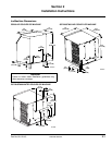
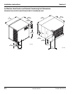
Section 2 Installation Instructions
Part No. 80-1214-3 2-7
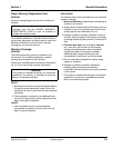
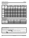
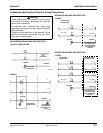
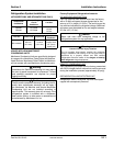
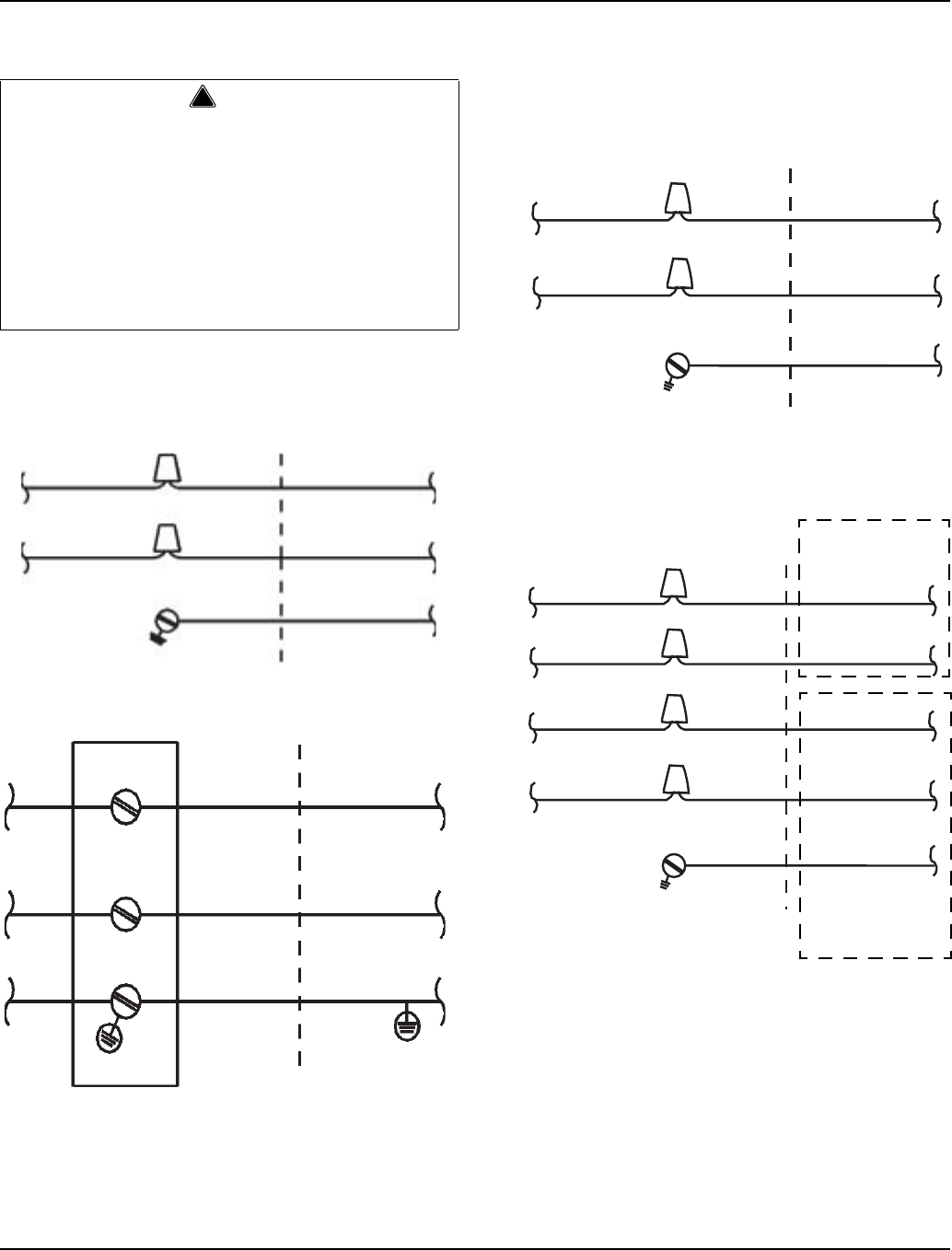
Ice Machine Head Section Electrical Wiring Connections
QC700/QF800 ICE MACHINE HEAD SECTION
115/1/60 or 208-230/1/60
230/1/50
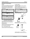
QF2200 ICE MACHINE HEAD SECTION
115/60/1
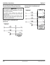
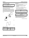
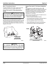
QF2300 ICE MACHINE HEAD SECTION
115/60/1
!
Warning
These diagrams are not intended to show proper
wire routing, wire sizing, disconnects, etc., only the
correct wire connections.
All electrical work, including wire routing and
grounding, must conform to local, state and national
electrical codes.
Though wire nuts are shown in the drawings, the ice
machine field wiring connections may use either
wire nuts or screw terminals.
L
1
L
1
N=115V
OR
L2=208-230V
GROUND
GROUND
ICE MACHINE
CONNECTIONS
SV1258
L
1
L
1
N
N
GROUND
GROUND
ICE MACHINE
CONNECTIONS
TO SEPARATE
FUSE/BREAKER.
DISCONNECT ALL
POLES.
SV1191
N = 115V
GROUND
GROUND
ICE MACHINE
CONNECTIONS
TO FUSE/BREAKER.
DISCONNECT ALL
LINE VOLTAGE DO
NOT DISCONNECT
GROUND.
L
1
L
1
N = 115V
C
1
C
1
N = 115V
GROUND
GROUND
ICE MACHINE
CONNECTIONS
TO FUSE/BREAKER.
DISCONNECT ALL
LINE VOLTAGE DO
NOT DISCONNECT
GROUND.
C
2
C
2
L
1
L
1
N = 115V
CONDENSING UNIT
CONNECTIONS
Revised 8/2003