


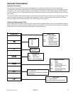
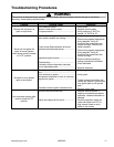

Component Testing Procedures
!
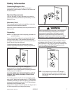
WARNING
To avoid risk of electrical shock, personal injury or death; disconnect power and shut off gas to unit before
servicing, unless testing requires power.
©2004 Maytag Services 16023219 13
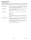
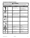
Illustration Component Test Procedure Results
Oven light housing Disconnect connector and test
resistance of terminals......................
Measure voltage at oven light...........
Verify bulb is plugged in properly.
Indicates continuity with bulb installed.
12 VAC, see wiring diagram for
terminal identification.
If no voltage is present at oven light,
check wiring or light switches.
Rocker switch Measure continuity of switch positions:
Closed..............................................
Open ................................................
Continuity
Infinite
Convection motor fan Verify supply voltage..........................
Check continuity of terminals, and
verify terminals are not shorted to
chassis...............................................
120 VAC
Approximately 80 Ω
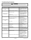
Controls Verify proper operation.
Open at 225°F, Closes at 165°F
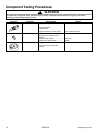
Griddle thermostat Verify supply voltage..........................
120 VAC
Oven thermostat Verify supply voltage..........................
120 VAC
Pressure regulator Verify gas pressure (WCP).
If on LP service, verify proper gas
supply conversion.
5
" Natural
10
" LP/Propane
GND
L or N
Input
Spark module
4 + 0
Test for voltage at terminals
L and N...........................................
Polarity and ground ........................
120 VAC
Not subject to polarity
Holder orifice Verify gas pressure (WCP).
Check orifice for debris.
5
" Natural
10
" LP/Propane
Clean as needed.
Spark ignition
electrode
Test for resistance of spark lead..........
Test ignitor to chassis..........................
Continuity
No continuity from ignitor to chassis.