


Disassembly Procedures
To avoid the risk of electrical shock, personal injury or
death; disconnect power to oven and shut off gas
supply before following any disassembly procedure.
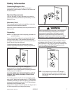
WARNING
!
16 16023219 ©2004 Maytag Services
Spark Module
1. Turn off gas and power supply to the oven.
2. Release control panel cover, see "Control Panel"
procedure, steps 1 through 5.
3. Locate spark module, looking through control panel
inside the burner box area at the rear of the unit.
4. Remove surface module located on top of spark
module, to gain access to spark module.
NOTE: Disconnect gas line at the surface valve for
module removal.
5. Remove screws securing spark module mounting
bracket to back of unit. Allow mounting bracket to fall
into burner box area.
6. Disconnect and label wire terminals from spark
module.
7. Release plastic tabs securing spark module to
mounting bracket.
8. Replace component and reverse procedures to
reassemble.
NOTE: Perform gas leak test to ensure unit will not leak
and unit operates properly.
Module(s) Removal
1. Remove top assembly pieces from module.
2. Disconnect and label wire terminals from module.
3. Disconnect gas line from the surface valve.
4. Raise upward on the rear of the module and side
back slightly to release module from orifice and
place to the side.
5. Reverse procedure to reassemble.
Oven Light Socket
1. Turn off gas and power supply to the oven.
2. Identify location of failed oven light.
• If located on an outside oven wall, remove
appropriate side panel, to gain access to oven
light, see "Side Panel" procedure.
• If located on oven interior wall,
3. Disconnect and label wire terminals from light
socket.
4. Open oven door and remove light lens cover from
light socket.
5. Release metal tabs on light socket and allow light
socket to release into the oven cavity area.
6. Replace component and reverse prodceure to
assemble.
Convection Fan
1. Open oven door and remove oven racks from the
oven cavity.
2. Remove screws securing convection fan cover to the
rear of the oven cavity.
3. Raise upward on convection fan cover to release
from supporting bracket.
4. Remove bolts securing convection fan to mounting
bracket.
5. Pull convection fan into oven cavity area and place to
the side.
6. Reach through convection fan hole located in the
rear of the oven cavity, following the wires.
7. Locate the terminal wire plug, sqeeze the side of the
terminal plug and pull to release.
8. Remove convection fan from the oven cavity.
9. Loosen set screw securing the fan blade to the
convection fan shaft and remove fan blade.
10.Remove nuts securing convection fan to the
mounting bracket.
11. Replace component and reverse procedures to
reassemble.
NOTE: When securing fan blade to the new convection
fan shaft allow approximately 1/4" from the
mounting bracket. Spin fan blade to ensure
blade spins freely.
Bake Burner and Ignitor
1. Shut off power and gas supply to unit.
2. Remove kick plate from under oven needing
servicing.
3. Disconnect and label wire terminals from gas valve.
4. Remove items and oven racks from oven cavity.
5. Grasp front corners of oven bottom, lift and pull
forward to remove from oven cavity.
6. Remove screw securing bake burner to oven
chassis, located at the rear of oven cavity.
7. Grasp burner and slide to the rear, while
maneuvering burner to either side to release from
burner orifice.
8. Remove screws and nuts securing ignitor to bake
burner.
9. Replace component and reverse procedure to
reassemble.