WARNING
REMOVE PLUG FROM WALL RECEPTACLE
AND SHUT OFF GAS SUPPLY BEFORE
ATTEMPTING ANY SERVICE ON THIS UNIT.
Servicing: To gain access to the drive components,
switches and wire guard plate, remove the right side
panel. To gain access to the gas burners, associated
components and burner controls remove the left side
panel. Each side panel is easily removed by removing the
two screws located on the underside of the unit.
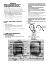
A On/Off Switch Replacement
1. Remove right side panel.
2. Remove two retaining screws from front panel.
3. Disconnect wiring harness from switch terminals.
4. Connect wiring harness to new switch and install
switch in panel. (Refer to wiring diagram)
B Bun/Toast Switch Replace-
ment
1. Remove right panel.
2. Disconnect wiring harness from switch terminals.
3. Depress two spring clips on top of switch and tilt
switch forward.
4. Insert the new switch into the panel opening, snapping
snugly into place.
5. Reconnect the wiring harness to the terminals. (Refer
to wiring diagram)
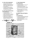
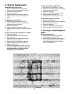
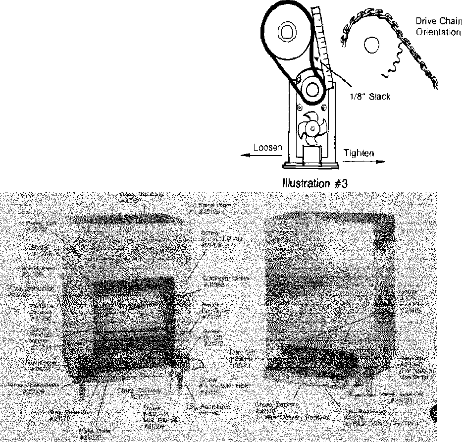
C Gearmotor Replacement
(Refer to illustrations 3 & 5)
1. Remove right side panel.
2. Disconnect motor lead wires from the terminal block
and on/off switch.
3. Remove the two nuts at the bottom of the motor
mounting plate and slide plate to the left. Disen-
gage drive chain from sprocket and remove from
weld bolts.
4. From the back of the plate, remove the four
screws holding the gearmotor.
5. Using a 1/16” Allen wrench, loosen sprocket
locking Allen screws and remove sprocket from
shaft.
6. Fasten new gearmotor to motor mounting plate.
7. Place motor mounting plate on weld bolts,
replace nuts. Do NOT tighten.
8. Slip sprocket on gearmotor shaft with hub facing
outward, mesh with drive chain, align with
sprocket clutch and tighten Allen screws.
9. Remove drive chain slack by sliding the mounting
plate to the right. Tighten nuts on motor mount-
ing plate.
10. Connect motor leads to terminal block and on/off
switch.
11. Replace side panel.
2


