8
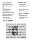
Q Burner Replacement
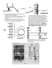
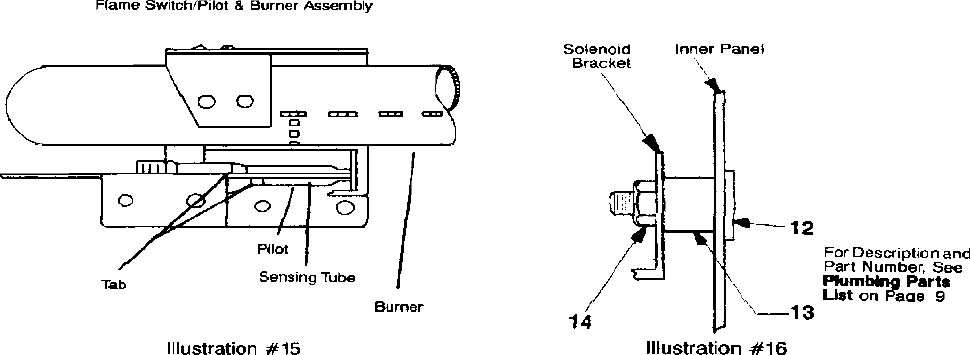
(Refer to illustration 15 & 17)
1. Loosen nut holding burner lock plate.
2. Remove wires from underside of pilot flame switch.
3. Using a screwdriver, press spring catch on side of
flame switch, snap ceramic base up and out of
bracket.
4. Using a 7/16” open end wrench, loosen pilot tube
compression nut at the burner. CAUTION: Pilot
orifice is loose in end of pilot.
5. Move pilot tube to the side and out of the way.
6. Lift burner to clear orifice and slide burner out.
7. Remove pilot bracket, containing pilot flame switch
assembly by removing screws fastening pilot bracket
to burner.
8. To install new burner, first place pilot bracket,
containing pilot flame switch assembly, on burner
and fasten with retaining screw.
9. Check that pilot flame switch assembly is parallel to
the burner in both the horizontal and vertical plane
and that sensing tube is locked even with the end of
pilot. (Illustration 15)
10. Insert burner into opening, slide along channel until
flat end of burner is fully seated in slot of right interior
wall.
11. Seat burner over orifice.
12. Drop burner lock plate to seat firmly over burner,
tighten nut to secure in place.
13. Place pilot tube in pilot and join by tightening com-
pression nut. CAUTION: Be sure pilot orifice is
positioned in end of pilot.
14. Snap flame switch ceramic into bracket and place
wires on terminals.
R Burner Replacement
(Follow procedures in Section Q)
Sub Assembly Components
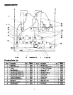
(Refer to illustrations 15, 16 & 17)
NOTE: The sub assembly contains the components that
direct and control gas flow to the burners. All threaded
fittings, with the exception of compression fittings and
orifices, should be coated with rectorseal #5 thread
sealing compound during installation.
S Sub Assembly Removal
(Refer to illustration 17)
1. Remove thermostat knob.
2. Remove union on intake pipe.
3. Remove pilot tube compression fittings at pilot flame filter
assembly.
4. Loosen burner lock plate nuts.
5. Bend capillary retainer clamp to achieve clearance and
slip tube from under clamp.
6. Remove wire connections from flame switches and
solenoid valves.
7. Carefully slide thermostat bulb from holder. CAUTION:
Avoid sharp bends or kinks in the capillary tube and
bulb that will create restriction, preventing proper
thermostat operation.
8. Remove the two nuts holding intake pipe to base plate.
9. Remove two nuts from each solenoid bracket, making
sure spacers remain in place. (Illustration 16)
10. Raise burners to clear orifices, tilt top of the sub assembly
to clear solenoid brackets from weld bolts, then move sub
assembly to rear until thermostat shaft clears front of
toaster.
11. Angle front of sub assembly outward and slide out of
toaster.
T Sub Assembly Installation
(Refer to illustration 17)
1. Slip intake pipe through rear opening far enough to allow
thermostat shaft to clear front of toaster and into front
opening.
2. Simultaneously, position solenoid brackets and intake pipe
over weld bolts. (Make sure spacers are in place on the
solenoid brackets). (Illustration 16) Install nuts and
tighten.
3. Carefully insert thermostat bulb into holder, dress capillary
tube and place under clamp. Bend clamp to secure tube.
4. Align burners over orifices, position burner lock plates and
tighten nuts.
5. Attach pilot tubes with compression fittings at pilot flame
filter assembly.
6. Slip wire connections on pilot flame switches and solenoid
valves. (Refer to wiring diagram)
7. Install union between intake pipe and pressure regulator.
8. Replace thermostat knob.
9. Turn on shut-off valve, light pilots and operate toaster.
CHECK ALL CONNECTIONS FOR LEAKS USING
SOAP SOLUTION.


