


6
SECTION 1
DESCRIPTION
III. COMPONENT FUNCTION
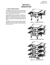
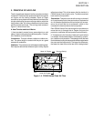
A. Conveyor Motor and Conveyor Belt
The conveyor belt is driven by a variable-speed electric
motor (Figure 1-7) operating through a gear reducer. The
motor speed is controlled by a digital control. The stain-
less-steel wire belt can travel in either direction at variable
rates ranging from 3 minutes to 30 minutes; this is the time
that a product can take to pass through the oven.
B. Blower Fan
The blower fan is located at the rear of the oven. This
blower forces heated air through the air fingers. The
BLOWER switch must be set to “ON” or “I” for oven
warmup and baking.
C. Electric Heaters
There is one heater element mounted on the inside of the
rear panel. The element is connected to an electrical
control which is energized by the temperature controller.
If the pilot flame does not light or a loss of flame occurs,
the main gas valve closes.
The main burner gas is extinguished when the HEAT
switch is set to “OFF” or “O”.
D. Window
A window on the front of the oven permits viewing the items
being baked and provides access to the oven for items that
do not require full baking time, such as sandwiches,
cookies, small items, or cheese-melting processes.
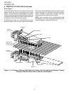
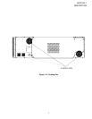
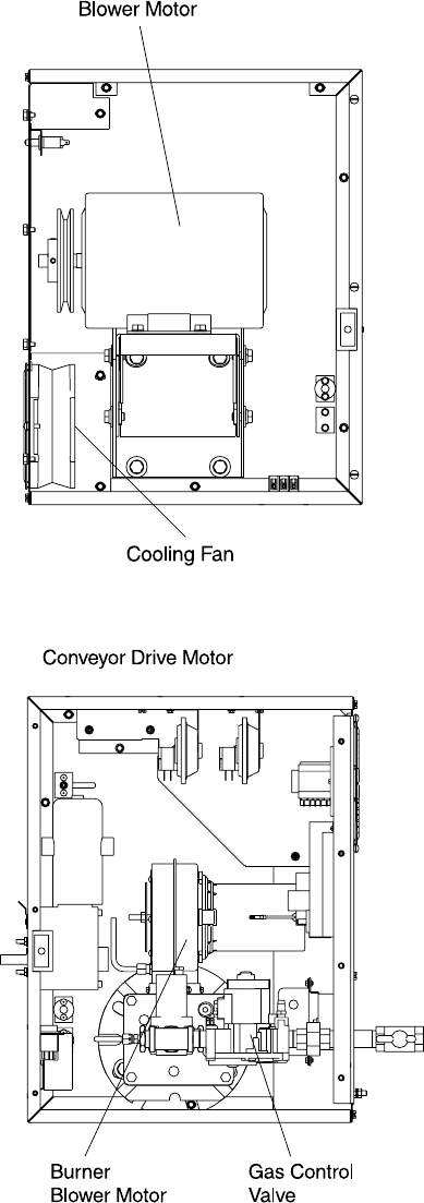
E. Cooling Fan — See Figure 1-8
The cooling fans are located in the back of the oven.
These cooling fans draw air through its grille, blowing it
through the blower motor compartment and the control
compartment into the oven top and exhausted out the front
louvers.
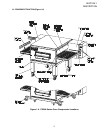
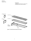
F. Air Fingers and Blank Plates - See Figure 1-9
F1. Air Fingers
An Air Finger Assembly is made up of three parts:
1.Outer Plate - The Outer Plate is the removable covering
with tapered holes, which direct the air stream onto the
product being baked.
2. Inner Plate -The perforated Inner Plate is vital in forming
the unique air jets. It must be assembled into the manifold
with its holes aligned with the holes of the outer plate.
3. Manifold - The Manifold is the assembly which slides
on tracks into the oven plenum.
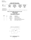
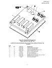
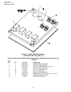
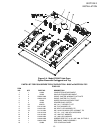
Figure 1-7. Machinery Compartment
Components
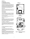
Left Control Box
Right Control Box