


SECTION 2
INSTALLATION
19
III. ELECTRICAL CONNECTION
INFORMATION FOR PS540-SERIES
OVENS.
WARNING
Authorized supplier personnel normally accom-
plish the connections for the ventilation system,
electric supply, and gas supply, as arranged by
the customer. Following these connections, the
factory-authorized installer can perform the initial
startup of the oven.
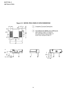
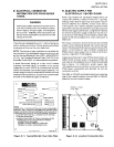
Check the oven data plate (Figure 2-11) before making any
electric supply connections. Electric supply connections
must agree with data on the oven data plate.
NOTE: The electric supply installation must satisfy the
requirements of the appropriate statutory authority, such
as the National Electrical Code (NEC), ANSI/NFPA70,
(U.S.A.); the Canadian Electrical Code, CSA C22.2; the
Australian Code AG601; or other applicable regulations.
A fused disconnect switch or a main circuit breaker
(customer furnished) MUST be installed in the electric
supply line for each oven; it is recommended that this
switch/ circuit breaker have lockout/tagout capability. The
electric supply connection must meet all national and local
electrical code requirements. Copper is the recommended
material for the electrical supply conductors.
IV. ELECTRIC SUPPLY FOR GAS-
HEATED OVENS
Supply voltages for all gas ovens (except one 200 - 220V
oven for export) can range from 208 to 240VAC, 1 phase.
Ampere requirements for each oven can be handled via a
fused disconnect switch or main circuit breaker.
NOTE: The electric supply installation must satisfy the
requirements of the appropriate statutory authority, such
as the National Electrical Code (NEC), ANSI/NFPA70,
(U.S.A.); the Canadian Electrical Code, CSA C22.2; the
Australian Code AG601; or other applicable regulations.
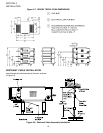
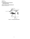
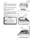
The supply conductors must be of the size (#14 AWG,
copper) recommended. (Refer to the wiring diagrams of
Section 7.) All gas oven electric supply connections are
made via the electrical junction box on the rear of the oven
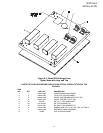
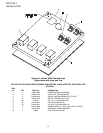
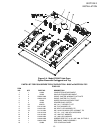
(Figure 2-12). The power lines then connect through an
oven safety switch (on the control console door frame) to
the oven circuits. Opening the door interrupts electric
power to the oven.
CAUTION
Before connecting incoming power to the oven,
measure the voltage of each input leg to
neutral. The expected voltage is approximately
120 volts. Any voltage reading exceeding 130
volts indicates that the supply has a ‘high’ leg.
CONNECTING A ‘HIGH’ LEG TO THE OVEN
VOIDS ALL OVEN WARRANTIES. Connecting
a ‘high’ leg to the black lead of the oven can
severely damage the oven’s electrical and
electronic components.
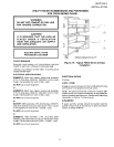
CAUTION
DO NOT CONNECT BLACK
WIRE TO HIGH LEG.
VOLTAGE OF THE BLACK AND
WHITE WIRES MUST BE NO
HIGHER THAN 130 VAC
Contact an electrician or the electric power supply com-
pany to remove the ‘high’ leg from the electric supply
line(s) to the oven.
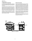
In the junction box on the rear of the oven, connect one
208 - 240V supply line to the black wire and the other
208 - 240V supply line to the red wire. Connect the
supply neutral line to the white wire. Connect the
electric supply ground wire to the oven ground screw
located in the main junction box. If necessary, have
the electrician supply the ground wire.
Do NOT use the
wiring conduit or other piping for ground connections!
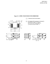
Figure 2-11. Typical Gas Oven Data Plate