


Revision Record........................................................................................................... i
Limited Warranty......................................................................................................... iii
Foreward ...................................................................................................................... iv
INTRODUCTION .......................................................................... 1
GENERAL .................................................................................... 2
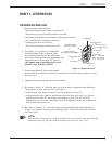
PART 1: OPERATION ................................................................... 3
PART 2: INSTALLATION AND MAINTENANCE ............................ 8
PART 3: REPLACEMENT PARTS .................................................. 11
PART 4: ELECTRICAL SCHEMATICS ........................................... 39
TABLE OF CONTENTS
v
TABLE OF CONTENTS PAGE
LIST OF FIGURES
Figure 1.1 – Operations Detail ................................................................................... 3
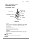
Figure 1.2 – Control Panel Detail ............................................................................... 7
Figure 3.1 – Hood and Tank ........................................................................................ 12
Figure 3.2 – Door Handle and Springs........................................................................ 14
Figure 3.3 – Door Switch and Block........................................................................... 16
Figure 3.4 – Tracks and Screens.................................................................................. 18
Figure 3.5 – Wash and Rinse Spray Arms .................................................................. 20
Figure 3.6 – Water Tank Components ......................................................................... 22
Figure 3.7 – Drain Assembly ...................................................................................... 24
Figure 3.8 – Wash and Rinse Piping ........................................................................... 26
Figure 3.9 – Wash Pump Assembly ............................................................................ 28
Figure 3.10 – Booster Assembly ................................................................................... 30
Figure 3.11 – Water Inlet Piping ................................................................................... 32
Figure 3.12 – Control Panel .......................................................................................... 34
Figure 3.13 – Control Cabinet....................................................................................... 36