


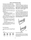
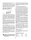
Check Out - Flame Failure Safety Device
Before placin
g
the refri
g
erator into operation, the
g
as safet
y
device must be tested
(
see Operatin
g
In-
structions on pa
g
e 13
)
. The purpose of the
g
as
safet
y
device is to prevent the escape of unburned
g
as from the burner if the burner flame is extin-
g
uished. Once a flame is established, close the man-
ual shut-off valve of the refri
g
erator. The flame will
extin
g
uish and i
g
nition spark will continue. Wait a
minimum of four
(
4
)
minutes and re-open the manual
shut-off valve. The burner flame will not re-establish,
indicatin
g
the
g
as safet
y
control is functional.
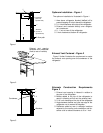
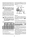
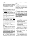
Door Panel Installation
The Norcold refri
g
erator doors provide slots for in-
sertin
g
decorative panels. Installation of the panels is
accomplished b
y
removin
g
the handle assembl
y
, in-
sertin
g
the decorative panel, and re-insertin
g
the
handle assembl
y
. This procedure applies to both
doors.
(
See Fi
g
ure 12
)
The frame slots are desi
g
ned to accept panel thick-
ness up to 3/16" maximum.
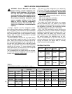
TABLE 4
PANEL DIMENSIONS
462, 463 482, 483
Upper Door 19 11/16" x 16" 19 11/16" x 16"
Lower Door 19 11/16" x 32 1/4" 19 11/16" x 39 1/4"
442, 443 452, 453
Door Panel 19 11/16" x 27 1/4" 19 11/16" x 39 1/4"
INSTRUCTIONS
1. Prepare panel b
y
cuttin
g
to size indicated in ac-
compan
y
in
g
chart.
(
See TABLE 4
)
2. Remove handle assembl
y
(
A
)
b
y
removin
g
four
screws
(
B
)
.
(
See Fi
g
ure 12
)
3. Slide panel into frame slots.
4. Replace the handle assembl
y
.
Instructions for Reversing Door Swing
Your refri
g
erator is e
q
uipped with convertible door
hin
g
es. The hin
g
in
g
of the doors can be chan
g
ed to
the opposite side an
y
time
y
ou wish.
TOOLS REQUIRED
Phillips Screwdriver - Size #2
Two Slotted Screwdrivers
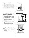
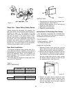
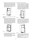
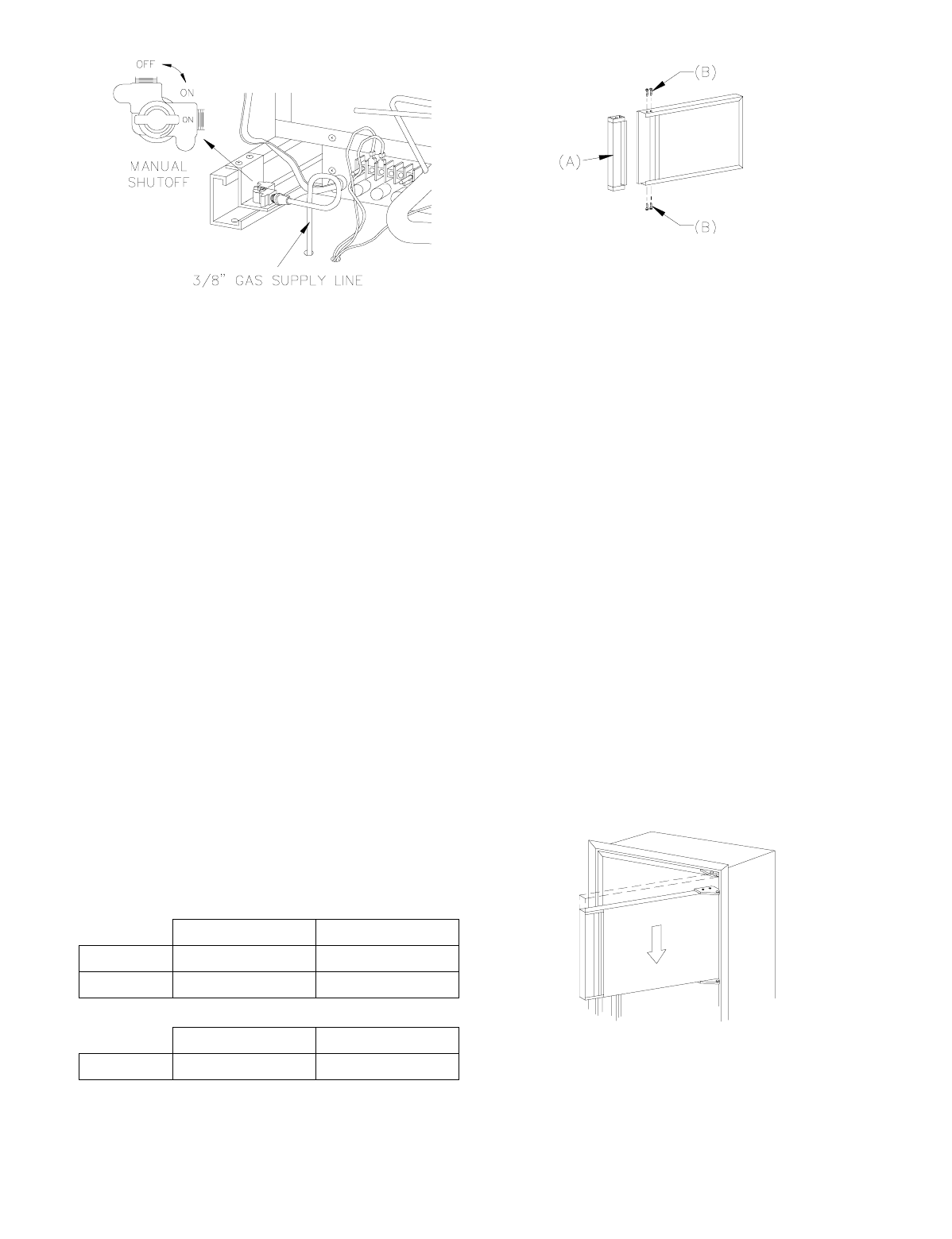
REMOVING THE DOORS
1. Remove all items of food,
j
uices, etc., from the
doors. Remove the
j
uice rack and stora
g
e bins.
Close both doors before removin
g
hin
g
e pins.
2. Remove the top hin
g
e pin usin
g
one of the slot-
ted screwdrivers. Remove the center hin
g
e pin
(
both pieces
)
usin
g
the two slotted screwdriv-
ers; one on each end of the pin. Lastl
y
, remove
the bottom hin
g
e pin. Be sure to save the pins
for reassembl
y
later.
(
See Fi
g
ure 19
)
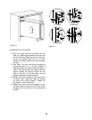
3. Remove the upper door b
y
openin
g
the door
sli
g
htl
y
and pullin
g
the bottom of the door awa
y
from the refri
g
erator. Allow enou
g
h room to
slide the door down off of the upper hin
g
e pin
shoulder.
(
See Fi
g
ure 13
)
Fi
g
ure 11
Fi
g
ure 12
Fi
g
ure 13
11