


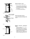
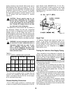
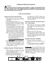
Optimum Installation - Figure 1
The optimum installation is illustrated in Fi
g
ure 1.
1. Area above refri
g
erator blocked
(
baffled
)
off to
prevent trappin
g
of hot air above the refri
g
erator.
2. 0 -1/4 inch clearance at the top of the refri
g
erator.
3. Exhaust vent centered directl
y
over refri
g
era-
tor’s condenser.
4. 0 - 1 inch at rear of the refri
g
erator.
5. 0 inch clearance at bottom of refri
g
erator.
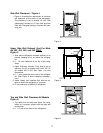
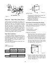
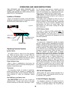
Exhaust Vent Centered - Figure 2
Fi
g
ure 2 further illustrates the re
q
uirement to center
the exhaust vent openin
g
over the condenser of the
refri
g
erator.
.
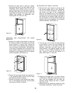
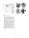
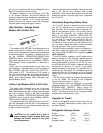
Alternate Construction Requirements
Figure 3
1. Exhaust vent openin
g
is inboard in relation to
the rear of the refri
g
erator.
2. Baffles added to the top of the refri
g
erator to
assist in directin
g
air flow out the exhaust vent.
3. 0-1/4 inch clearance at the top of the refri
g
erator.
4. An
g
le between baffles and rear top ed
g
e of the
refri
g
erator not to exceed 45 de
g
rees.
5. Deflectors added at rear in strate
g
ic locations
ad
j
acent to the coolin
g
units condenser and ab-
sorber coils to reduce clearance to 0 to 1 inch.
4
5
3
Condenser
(
source of
re
j
ected heat
)
Absorber
(
source of
re
j
ected heat
)
Air flow path
1
2
Fi
g
ure 1
5
Absorber
1
2
4
Condenser
2
3
Fi
g
ure 3
Exhaust vent openin
g
centered over condenser
(
front to rear of vehicle
)
Fi
g
ure 2
6