


OPERATING AND USER INSTRUCTIONS
THIS APPLIANCE HAS BEEN DESIGNED FOR
STORAGE OF FOODS, STORAGE OF FROZEN
FOODS, AND MAKING ICE WHEN INSTALLED AS
DIRECTED BY THIS MANUAL.
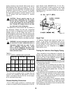
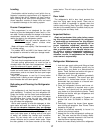
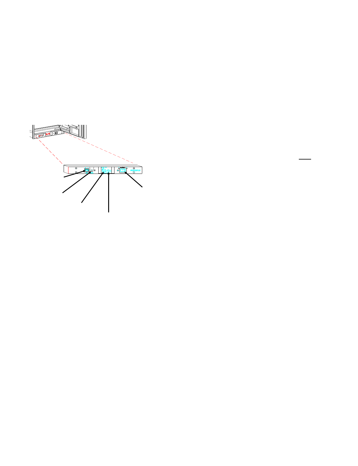
Location of Controls
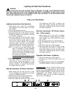
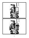
Figure 18 illustrates the location of the 400 Series
refrigerator’s operating controls. All operating controls
are conveniently located below the door.
Operating Controls Function
Ignition Switch
The ignition switch is used for the Gas operation
only. When the ignition switch is turned "ON", the
switch will illuminate indicating that 12 volt DC is
available and being supplied to the electronic ignition
which generates ignition spark to the burner.
Flame Indicator Lamp
When a flame is established at the burner, the
Flame Indicator Lamp will illuminate indicating the re-
frigerator is operating on gas.
Thermostat
The thermostat controls all modes of operations,
thereby eliminating the necessity of resetting each
time a different power source is selected. Rotate the
knob clockwise to make the refrigerator cabinet
colder.
Gas ON/Electric and Safety Valve
Gas ON/ELECTRIC
allows the user to select an
operating mode. For gas, push and turn the knob
counter-clockwise until the knob is pointing to "GAS".
For AC electric, push and turn clockwise until the
knob is pointing to"ELEC". Note, upon release the
knob will move towards you, indicating that the oper-
ating control is locked into the AC electric mode.
Safety Valve
- During the gas ignition process, the
safety valve knob must be held in until a flame is
established at the burner.
The safety valve is designed so that any loss of
flame will stop the gas flow to the burner. It is con-
trolled by means of a thermocouple that is positioned
in the flame. As long as a flame is detected by the
thermocouple, the valve will remain open. Upon
flame failure, the valve closes, shutting off the gas
flow to the burner.
AC/DC Selector Switch
This switch is utilized on 3-Way models
only
. The
switch selects either 120 volt AC or DC electric
modes of operation. The center position of the switch
is a "Stand-By" mode which will temporarily turn off
the electric positions.
Gas Operation
The gas burner is designed to operate on propane
gas only. The gas control is equipped with an ignition
relighter, offering the features of automatic re-ignition
in case of flame blowout, positive flame sensing, and
easier gas start-up. The ignition relighter is powered
by 12 volts DC and is controlled by the ignitor switch
located on the control panel. When the switch is in
the "OFF" position, no ignition spark is present.
When the switch is in the "ON" position, the relighter
produces a rapid spark at the gas burner. The spark
occurs at a rate of 1 to 2 times per second until a
flame is present (Refer to "Lighting Instructions").
The spark continues until a flame is sensed or until
the ignitor switch is turned off. When the flame is
sensed, the relighter discontinues the spark and the
flame indicator illuminates. The flame indicator lamp
will cease to illuminate upon loss of burner flame.
During gas operation, the current draw for the re-igni-
tion system is very low, approximately 30 milliamps
(.030 amps).
120 Volt AC Operation
While parked, the coach normally operates from a
120 volt AC source. The refrigerator can be very eas-
ily switched to AC operation.
!2 Volt DC Electric Operation
The refrigerator receives its DC power from the ve-
hicle’s 12 volt system; either an auxiliary battery, a
converter, or the engine battery. The 12 volt DC sys-
Ignition Switch
Flame
Indicator Lamp
Thermostat
Gas On/Electric
and Safety Valve
AC/DC Selector Switch
3-Way Models Only
Figure 20
15