11
Plumbing
Air System
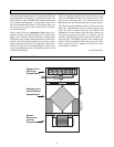
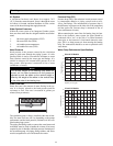
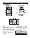
A circulation fan draws cool house air at approx. 70°F
(21°C) from the return ductwork, forces it through the water
coil where it is heated, and then distributes it to the various
rooms of the house through the supply ductwork.
Water System Pressures
Within the water system of an Integrated Combo system,
there are three terms that the designer/installer must under-
stand.
1. Hot water supply temperature (EWT)
2. Hot water flow rate (GPM)
3. Air handler return temperature
4. Air handler flow rate (CFM)
Head Pressure
Head pressure is the pressure created by the circulation
pump to push water through the piping system. It is this
pressure which is used to overcome the resistance to water
flow (friction) caused by the water pipe and fittings. It is
similar in concept to the external static pressure in an air
duct system. Head pressure is measured in feet of water
(millimeters of water).
Water Flow Rate
Water flow rate is the amount of water flowing in the sys-
tem. It is directly related to the head pressure and the
resistance to flow. Flow rate is measured in gallons per
minute (liters per minute).
The circulation pump is factory installed within the air han-
dler. The water flow rate will vary depending on the pumps
performance and the head pressure (resistance) of the com-
plete heating loop system.
The piping and fittings used to connect the water heater and
air handler must be sized to handle the volume of hot water
required by the air handler within the pressure limitations of
the circulation pump. All piping, fittings solders, and fluxes
must be acceptable for use with domestic hot water.
Pressure Drop (PD)
Pressure drop (PD) is the reduction in total pressure caused
by components added to a piping system such as coils,
valves, and fittings. The measurement of pressure drop is
the difference in pressure on the inlet side of the component
and the outlet side. Pressure drop is measured in feet of
water (millimeters of water).
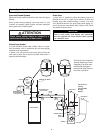
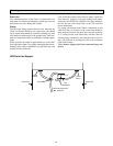
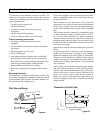
When connecting the water lines for heating loop (air han-
dler) to the domestic water system, the pipes should be
connected with a “tee” to the side of a vertical domestic
water pipe or the bottom of a horizontal domestic water
pipe. This is to help prevent air from entering the heating
loop. The connections should be as near as practical to the
water heater.
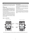
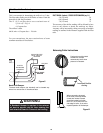
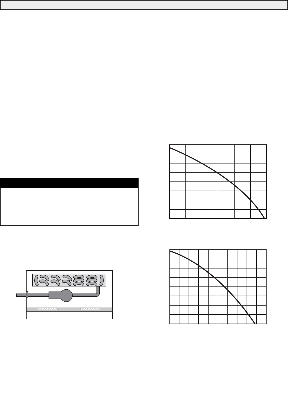
Water Pump Performance Specifications
NOTE
The vertical height of the heating loop does not
impact on the head pressure as the pressure
required to push the water up the vertical height is
offset by the weight of the water in the vertical drop
on the other side of the heating loop.
16
14
12
10
8
6
4
2
0
Capacity on U.S. gpm
S2 and S4 Models
1 2 4 6 8 10 12
Total Head in Feet
L2 and L4 Models
1 2 4 6 8 10 12 14 16 18 20
16
14
12
10
8
6
4
2
0
Capacity on U.S. gpm
Total Head in Feet


