


13
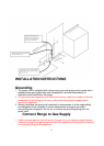
2. Install a manual valve in an accessible location in the gas line external to the
appliance tor the purpose of turning on or shutting off gas to the appliance.
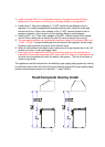
3. Install male ½” flare union adapter to ½” NPT internal thread elbow at inlet of
regulator. On models equipped with standard twin burners, install the male pipe
thread end of the ½”flare union adapter to the ½” NPT internal thread at inlet of
pressure regulator. Use a wrench on the regulator fitting to avoid damage.
4. Install male ½” or ¾” flare union adapter to the NPT internal thread of the manual
shut-off valve, taking care to secure the shut-off valve to keep it from turning.
5. The gas supply pressure for checking the regulator setting is 6in (Nature Gas) and
11inch(LP gas)connect flexible gas line connector to the regulator on the range.
Position range to permit connection at the shut-off valve.
6. When all connections have been made, make sure all range controls are in the “off”
position and turn on main gas supply valve.
7. Leak testing of the appliance shall be conducted according to the manufacture’s
instructions .Use some soap water (50% water and 50% soap) or a leak detector at
all joints and connections to check for leaks in the system. Do not use a flame to
check for gas leaks.
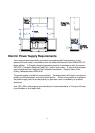
The appliance must be isolated from the building’s gas supply piping system by closing
its individual manual shut-off valve during any pressure testing of the gas supply piping
system at test pressure equal to or less than ½ psig (3.5kPa).
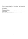
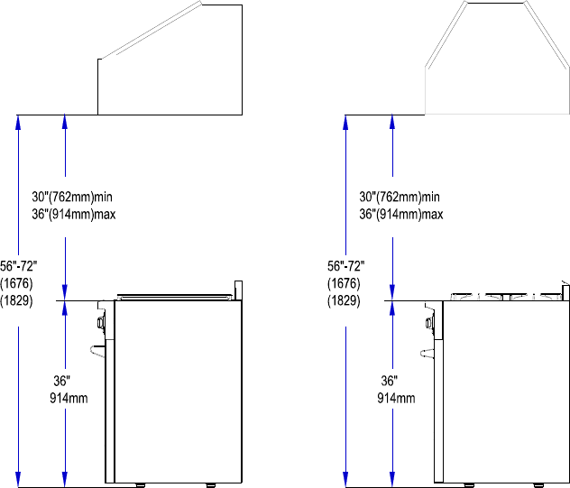
Hood/Composite Overlay Install