


8
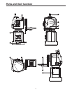
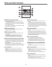
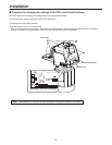
Rotary head
This rotates in the horizontal direction.
Pedestal
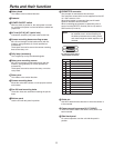
POWER ON/OFF switch
Where a switch is pushed in, the unit’s power is turned
on, and the unit’s power is turned off after the switch has
jumped out.
AC inlet [AC IN] (AC 3-point inlet)
Connect the accessory AC power cable to this inlet.
Camera mounting base mounting screws
M522 mm hexagon socket head screws (with flat
washers, spring washers) (3 of each provided as
accessories)
These parts are used to secure the camera mounting
base to the rotary arm.
Tally lamp (accessory)
This is lighted up red by the selected signals.
Rotary arm mounting screws
M522 mm hexagon socket head screws (with flat
washers, spring washers) (4 of each provided as
accessories)
These parts are used to secure the rotary arm to the
rotary head.
Rotary arm
This rotates in the vertical direction.
Camera mounting base
Mount the convertible camera or multi-purpose camera
on this base.
Pan-tilt head mounting holes
These four holes are used when installing the pan-tilt
head.
Bottom panel
Use the unit with this panel in position.
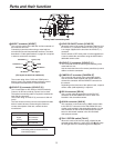
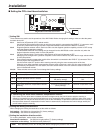
PROMPTER connector
The prompter is connected to this connector.
The maximum current which can be supplied from the DC
12 V OUT socket is 2.5 A.
When the prompter is connected, the pan-tilt head’s
speed is reduced to about one-third.
When connecting the prompter, be absolutely sure to
short-circuit the DETECT terminal (Pin No.14) and the
GND terminal (Pin No.15).
Note
Consult your dealer when a prompter is to
be installed since it will be necessary for
the balance between the mounting fixture
and overall weight and other aspects to be
checked.
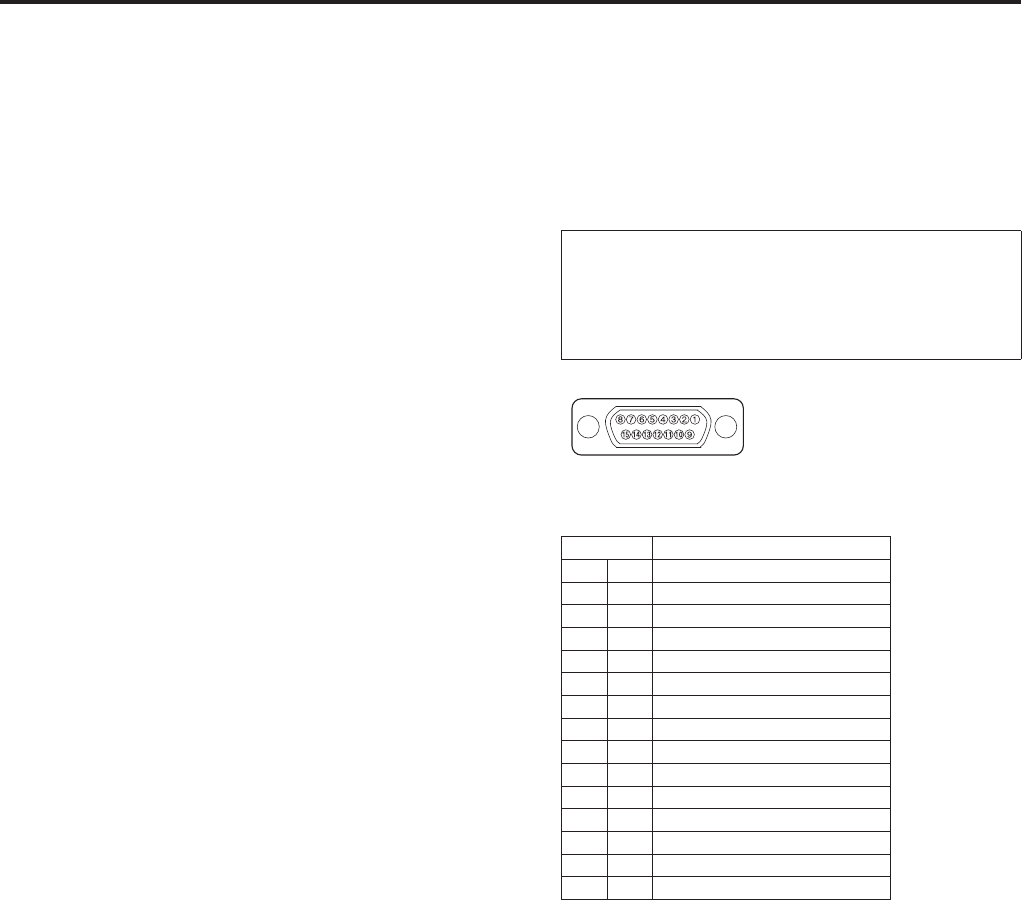
Pin layout as seen facing
the prompter connector
Pin No. Signal Name
1 – – –
9 – – –
2 PROMPTER VIDEO
10 PROMPTER VIDEO GND
3 – – –
11 – – –
4 DC 12 V OUT
12
– – –
5 GND
13
– – –
6 – – –
14 DETECT
7 – – –
15 GND
8 – – –
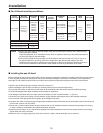
Guide pin
Use this to determine the direction in which the camera is
to be mounted.
Camera mounting screws (U1/4” 20UNC)
These are used to secure the camera firmly after it has
been mounted.
Side blank panel
For normal operation, use the unit with this panel in
position.
Parts and their function