


INSTALLATION
10 L20-294, rev. 0 (1/06)
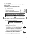
ON
OFF
T
P
O
L
I
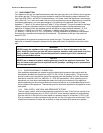
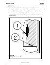
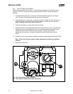
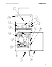
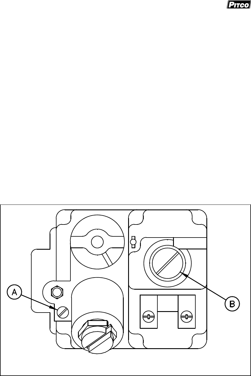
A) Pilot Adjustment (under cap screw)
B) Gas Pressure Adjustment (under cap screw)
1.9.3. PILOT FLAME ADJUSTMENT
Perform this procedure with the pilot lit. This procedure requires a DC voltmeter set to a
scale of 0-1000 mV. Using test leads with sharp probes will help in taking the required
readings.
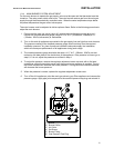
1. Locate the thermopile wires coming from the thermostat/limit box going to the gas
valve. The wire size decreases near the gas valve connections.
2. Using the positive (+) test probe, connect the probe to the high limit wire terminal. On
particular systems, pierce the high limit wire insulation, with the tip of the test lead
probe, at the gas valve safety magnet connection.
3. Connect the negative (-) test probe to the pilot tubing.
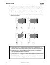
4. Remove the cap screw located below the pilot tubing on the gas valve. The pilot flame
adjustment screw is recessed behind this. Turning the pilot flame adjustment screw
clockwise lowers the pilot flame and millivolt output. Turning the pilot flame
adjustment screw counter- clockwise increases the pilot flame size and millivolt
output.
5. Rotate the screw in the direction needed to achieve a reading between 600 and 750mV.
Note: Allow 3 to 5 minutes between flame adjustments to allow the reading to
stabilize.
6. Replace the cap screw.