


68
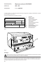
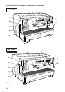
13. MACHINES WITH ALTERNATIVE GAS
HEATER VERSION
N.B. Installation of the machine and any
adjustment or adaptation to the type of gas
should be done by a technically qualified
person.
The machine leaves the factory all set for use with liquid
gas (GPL).
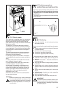
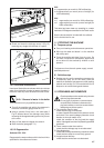
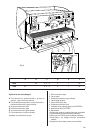
The gas regulator (1) is therefore fitted with the
appropriate injector shown in the table below:
The primary air intake regulator (2) is set with the
reference notch showing “GPL” corresponding te the
secuting screw (3).
The flame is regulated (minimum and maximum) to suit
this type of gas.
If the machine is to be used with a different type of gas,
it will be necessary to replace the injector in accordance
with the above table and to rotate the primary air
regulator (2), which, in the case of natural gas, will have
to be set with the reference notch showing “N”
corresponding to the securing screw (3).
To do this, it will of course be necessary to loosen the
securing screw (3) and to tighten it again after rotating
the primary air intake regulator (2).
Connections to mains gas, from the gas tap available
in the room to the valve fitted on the machine, must be
carried out in accordance with the regulations in force,
using a flexible pipe or a rigid pipe in annealed copper.
In the latter case, the special rubber-pipe fitting in
connected tightly to the valve by means of the biconical
nozzle and securing nut supplied.
The flexible pipe is fitted over the end of the mains outlet
and secured with the metal strip supplied.
Alternatively, the annealed copper pipe can be
connected up, again using the special biconical nozzle
and the appropriate nuts, directly to the valve.
Once the machine has been connected up to the gas
main, and after filling the boiler up with water in
accordance with the instructions in the booklet
(“INSTRUCTIONS FOR USE AND MAINTENANCE”),
the burner can be lit in the following manner:
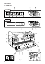
z Open the main gas tap.
z Press on the gas valve knob, on the machine rotate
it 90° anti-clockwise, and keep it pressed in. At the
same time, press the piezoelectric lighter one or more
times – the lighter knob bears a symbol resembling
a spark – until the burner lights up.
z Wair about 20 seconds, then release the valve knob
and the burner should stay lit – the flame is vidible
through the special hole in the panel behind the
dispenser units.
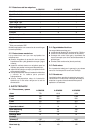
Model
Nominal
thermic
capacity
GPL
G30 - 29 mbar
Natural gas
G20 - 20 mbar
2 Gr.
2,5 KW
(2150 Kcal/h.)
75 102
3-4 Gr.
3,3 KW
(2850 Kcal/h.)
90 135
N.B.
Should the burner not light up, do not persist, but release
the valve knob, and then check that lighter spark on the
burner is in order and about 5 mm long.
Should the flame go out when te valve knob is released,
check the position of thermocouple and the circuit
connected to it.
The flame should be bright blue; if not, slightly regulate
the primary air intake (2) until the desired effect is
achieved.
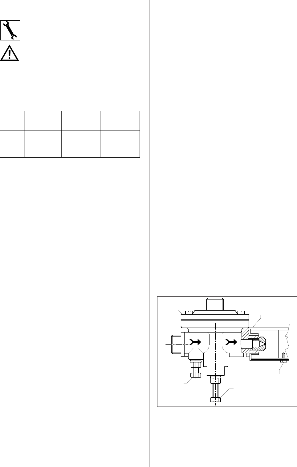
Wait until the machine has the correct pressure,
according to instructions. Otherwise, adjust the gas
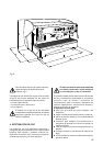
pressure regulator, which has two regulating screws.
The one that protrudes more (4) serves to regulate the
boiler’s operating pressure, while the other (5) serves
to set the flame at the minimum.
When the machine is pressurized, check to see that
the minimum flame is correct by adjusting the screw (4)
if necessary; after loosening the locking-nut, unscrew
the screw until it feels loose (the main gas-pipe is
closed), and check whether, under these conditions, the
low flame remains lit, thus acting as a pilot.
If the flame is too high, it will be necessary to regulate
screw (5), turning it slightly clockwise, of course after
having loosened the locking-nut. If, on the contrary, the
flame tends to go out, then regulate screw (5) by turning
it anti-clockwise, until a very low, but constant flame is
obtained. Having achieved this correct adjustment of
the minimum flame, hold the screw still and lock it with
the locking-nut.
Then rotate the screw (4) clockwise until there is a there
is a high flame, and wait for the boiler to reach the
desired operating pressure: if the flame dies down before
reaching the required pressure, tighten screw (4) further;
if the flame dies down at a higher pressure, then unscrew
the screw.
Check once or twice by opening the steam tap to release
the pressure in the boiler, then hold screw (4) still and
lock it with the locking-nut.
Fig. 13