


ELECTRICAL CONNECTIONS
GI~tx,h
witlr
yuu,
Iwal
utiliticsfor clootrionl codeswhich
apply in your
arpg
If thm are no
local codes, the Natronal Electmat Code,
ANSI’NFPA No. 70-l 987 must be followed. You can get a copy by
wrrtrng
National Fire Protection Association
Batterymarch Park
Quincy,
MA 02269
An adequate electrical supply and outlet must be used to operate
the electrrcal parts of your oven. The oven cord has three prong
plug and must be used with a properly grounded three hole outlet
with a standard 120 volt, 60 cycle AC household current.
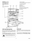
Install the electrical outlet belowtheoven on the right side. It should
be easily reached through cabinet doors below the oven. See
Figure 5.
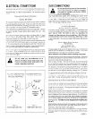
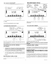
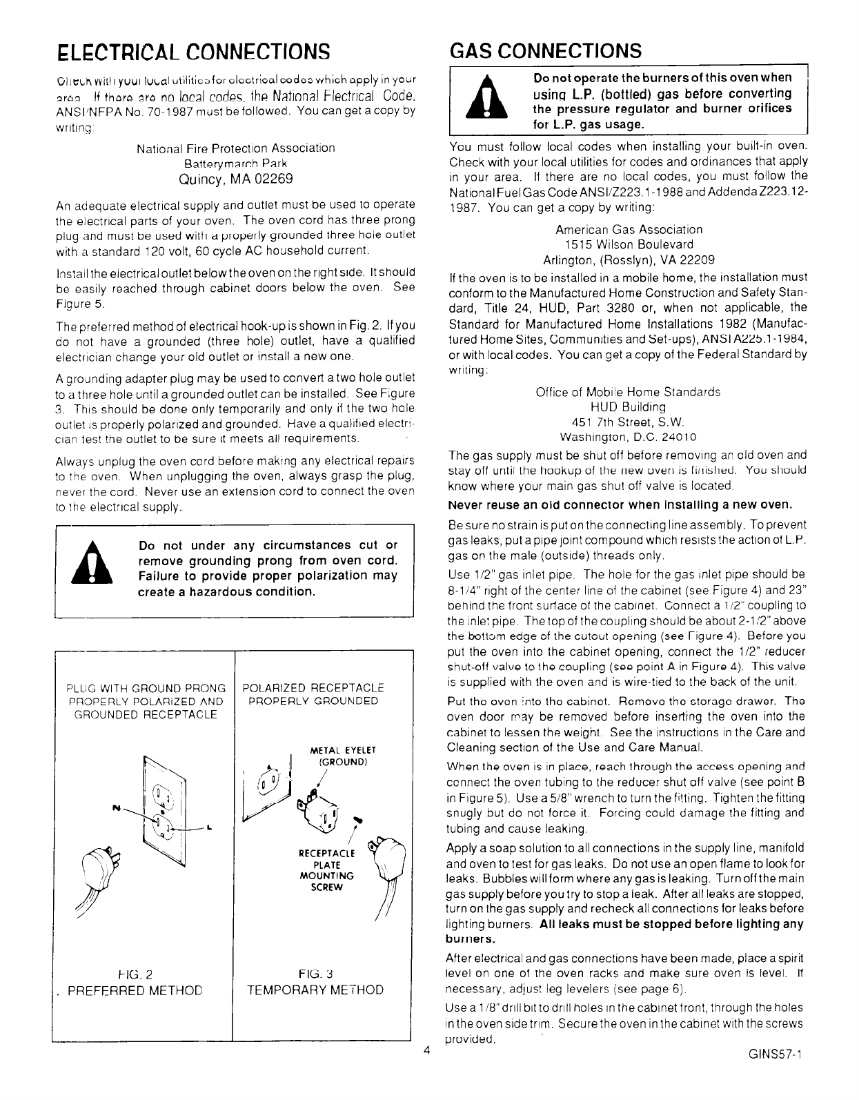
The preferred method of electrical hook-up isshown in Fig. 2. If you
do not have a grounded (three hole) outlet, have a qualified
electrrcian change your old outlet or install a new one.
A grounding adapter plug may be used to convert atwo hole outlet
to a three hole until a grounded outlet can be installed. See Figure
3. Thrs should be done only temporarily and only if the two hole
outlet IS properly polarized and grounded. Have a qualrfred electrr-
clan test the outlet to be sure it meets all requirements.
Always unplug the oven cord before makrng any electrical repairs
to the oven. When unplugging the oven, always grasp the plug,
never the cord. Never use an extensron cord to connect the oven
to the electrrcal supply.
Do not under any circumstances cut or
remove grounding prong from oven cord.
create a hazardous condition.
-z
PLUG WITH GROUND PRONG
PROPERLY POLARIZED AND
GROUNDED RECEPTACLE
FIG. 2
PREFERRED METHOD
POLARIZED RECEPTACLE
PROPERLY GROUNDED
METAL EYELET
MOUNTING
FIG. 3
TEMPORARY METHOD
4
GAS CONNECTIONS
A
Do not operate the burners of this oven when
using
L.P. (bottled) gas before converting
the pressure regulator and burner orifices
for I-P. gas usage.
You must follow local codes when installing your built-in oven.
Check with your local utilities for codes and ordinances that apply
in your area. If there are no local codes, you must follow the
NationalFuelGasCodeANSI/Z223.1-1988andAddendaZ223.12-
1987. You can get a copy by writing:
American Gas Association
1515 Wilson Boulevard
Arlington, (Rosslyn), VA 22209
If the oven is to be installed in a mobile home, the installation must
conform to the Manufactured Home Construction and Safety Stan-
dard, Title 24, HUD, Part 3280 or, when not applicable, the
Standard for Manufactured Home Installations 1982 (Manufac-
tured Home Sites, Communities and Set-ups), ANSI A225.1-1984,
or with local codes. You can get a copy of the Federal Standard by
writing:
Office of Mobrle Home Standards
HUD Building
451 7th Street, S.W.
Washrngton, D.C. 24010
The gas supply must be shut off before removing an old oven and
stay off until the hookup of the new oven is finished. You should
know where your main gas shut off valve is located.
Never reuse an old connector when installing a new oven.
Be sure no strain is put on the connecting line assembly. To prevent
gas leaks, put a pipe joint compound which resists the action of L.P.
gas on the male (outsrde) threads only.
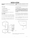
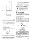
Use l/2” gas inlet pipe. The hole for the gas inlet pipe should be
8-li4” right of the center line of the cabinet (see Figure 4) and 23”
behind the front surface of the cabrnet. Connect a 112” coupling to
the inlet pipe. The topof the couplrng should be about 2-1 i2”above
the bo!tom edge of the cutout opening (see Figure 4). Before you
put the oven into the cabinet opening, connect the 112” reducer
shut-off valve to the coupling (see point A in Figure 4). This valve
is supplied with the oven and is wire-tied to the back of the unit.
Put the oven into the cabinet. Remove the storage drawer. The
oven door may be removed before inserting the oven into the
cabinet to lessen the weight. See the instructions in the Care and
Cleaning section of the Use and Care Manual.
When the oven is in place, reach through the access opening and
connect the oven tubing to the reducer shut off valve (see point B
in Figure 5). Use
a
5/8” wrench to turn the fi!ting. Tighten the fitting
snugly but do not force it. Forcing could damage the fitting and
tubing and cause leakrng.
Apply
a
soap solution to all connections in the supply line, manifold
and oven to test for gas leaks. Do not use an open flame to look for
leaks. Bubbles will form where any gas is leaking. Turn offthe main
gas supply before you try to stop a leak. After all leaks are stopped,
turn on the gas supply and recheck all connections for leaks before
lighting burners.
All leaks must be stopped before lighting any
burners.
After electrical and gas conneclions have been made, place asprrit
level on one of the oven racks and make sure oven is level. If
necessary, adjust leg levelers (see page 6).
Use a 1/8”drill bit todrill holes in thecabinet front, through the holes
in the oven side trim. Secure the oven in the cabinet with the screws
provided.
GINS57-1