


S3F84B8_ALL-IN-ONE IH COOKER_AN_REV 0.00 2 HARDWARE IMPLEMENTATION
2-5
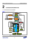
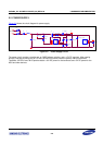
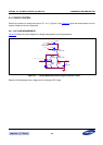
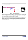
In Figure 2-1, SMPS stands for Switch Mode Power Supply. It provides +18V DC and +5V DC to the system.
Three out of four comparators are used in this solution: one for synchronization circuit and other two for surge
protection and IGBT over-voltage protection.
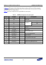
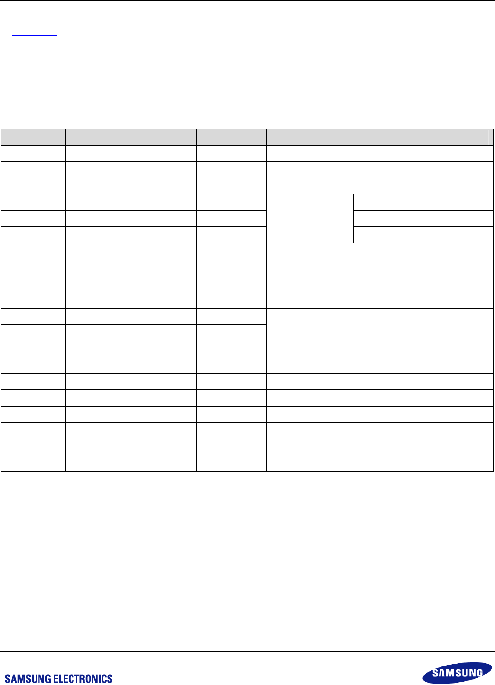
Table 2-1
shows the pin assignment while using S3F84B8 in IH cooker system.
Table 2-1 S3F84B8 pin assignment in IH cooker system
Pin No. Pin Names Pin Type Pin Assignment
1 VSS I Ground
20 VDD I Power input
4 P0.2 - Reserved
2 P0.0 O DIO
3 P0.1 O CLK
7 P0.5 O
Display Board
Connector
STB
8 P0.6 O Reserved
13 P2.1 O Reserved
5 P0.3/BUZ O Buzzer and Fan control
6 P0.4/PWM O IGBT control
9 P1.0/CMP0_P I
10 P1.1/CMP0_N I
Synchronization control
11 P1.2/CMP1_N I IGBT over-voltage protection
16 P2.4/CMP2_N I Surge protection
17 P2.5/ADC5 I System voltage measurement input
12 P2.0/ADC0 I IGBT temperature sensor input
19 P2.7/ADC7 I Pan temperature sensor input
18 P2.6/ADC6 I Amplified current signal input
14 P2.2/OPA_N I System current measurement input
15 P2.3/OPA_O O Operational Amplifier output