


List of Figures
Figure Title Page
Number Number
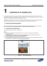
Figure 1-1 How IH Cooker Work
s ...................................................................................................................... 1-1
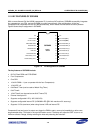
Figure 1-2 Pin Assignment in S3F84B8
............................................................................................................. 1-2
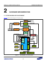
Figure 2-1 Block Diagram of IH Cooker Sys
tem ................................................................................................ 2-4
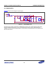
Figure 2-2 Power Suppl
y Circuit ........................................................................................................................ 2-6
Figure 2-3 Power Suppl
y Circuit ........................................................................................................................ 2-7
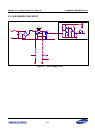
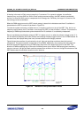
Figure 2-4 Waveform of the Sync
hronization Circuit ......................................................................................... 2-8
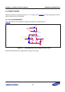
Figure 2-5 Voltage Measurement and
Surge Protection Circuit ........................................................................ 2-9
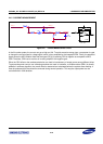
Figure 2-6 Current Measurement Circuit
.......................................................................................................... 2-10
Figure 2-7 Over-Temperature Protec
tion......................................................................................................... 2-12
Figure 2-8 Buzzer and Fan Control
.................................................................................................................. 2-13
Figure 2-9 Key and Display Circuit
................................................................................................................... 2-14
Figure 3-1 State Trans
ition Diagram.................................................................................................................. 3-1
Figure 3-2 Software Diagram
............................................................................................................................. 3-2
Figure 3-3 Interrupt Servic
e Routine Diagram ................................................................................................... 3-3
Figure 3-4 Fan and B
UZ Workflow..................................................................................................................... 3-3