


S3F84B8_ALL-IN-ONE IH COOKER_AN_REV 0.00 2 HARDWARE IMPLEMENTATION
2-12
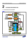
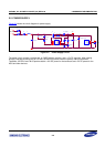
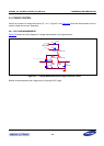
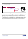
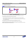
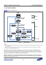
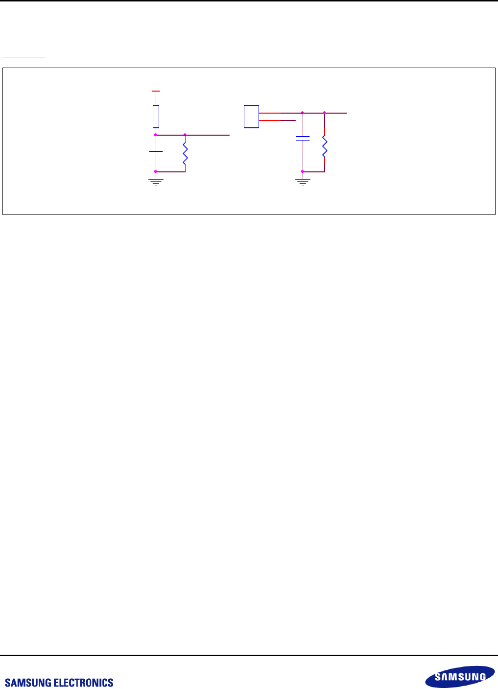
2.5.4 TEMPERATURE PROTECTION
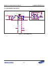
Figure 2-7
shows the circuit diagram for temperature protection.
C4
104
R5
10K
RT1
100K3950
IGBT_T
+5V
PAN_T
a) Pan temperature protectionb) IGBT temperature protection
C25
104
R29
3K
1
2
CN5
T_PAN
+5V
Figure 2-7 Over-Temperature Protection
RT1 is a thermistor located just beneath the IGBT. CN5 is the connector for the thermistor near the pan.
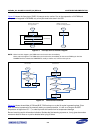
For IGBT temperature protection, there are two kinds of scenarios:
When the temperature rises above 85℃, the set level of output power will automatically downgrade.
When the temperature continues to rise above 90℃, the system will shut down and will remain in that state
until it is restarted manually.
For pan temperature, the system will be shut down when the temperature is over 230℃.
The threshold of protection level can differ, according to the different locations of the thermistor.
Meantime, when the sensed voltage level is close to 5V or 0V, the sensor can be viewed as broken. The whole
system then stops working until it is restarted manually.