


S3F84B8_ALL-IN-ONE IH COOKER_AN_REV 0.00 3 SOFTWARE IMPLEMENTATION
3-3
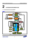
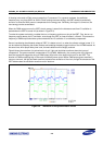
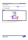
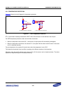
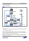
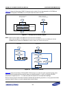
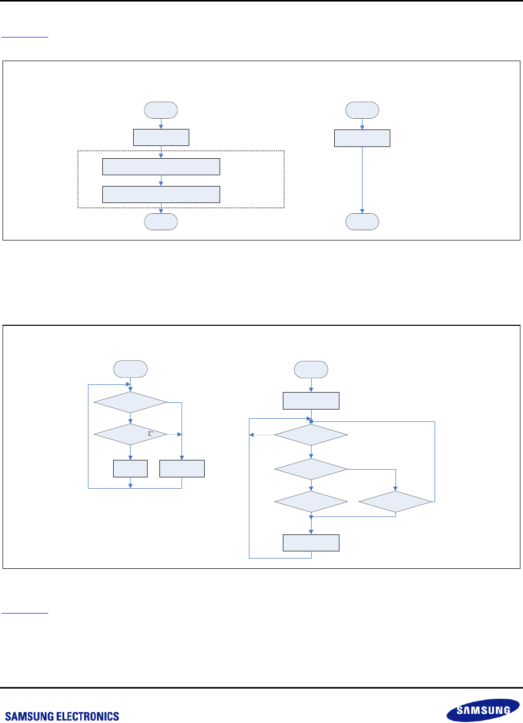
Figure 3-3 shows the flow chart of CMP1/2 interrupt service routine. Due to the cooperation of IH-PWM and
comparators integrated in S3F84B8, only a few jobs need to be done in the ISR.
Start
Clr pending bit
Set P0.4(PWM) to input without pull-up R
PWMCON = 0
End
Not mandatory
Start
End
Clr pending bit
CMP1INT ISR (hard lock)
For surge protection
CMP2INT ISR (soft lock)
For IGBT over voltage protection
Figure 3-3 Interrupt Service Routine Diagram
NOTE: When hard lock happens, the PWM returns to the safe value immediately.
When soft lock happens. The PWM returns to the safe value immediately for the current PWM cycle. And the
PWMDATA will be reloaded as PWMPDATA, usually a smaller one, from the next cycle on.
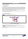
Fan On
Power flag = 0?
IGBT temp < 55
Fan Off
Start
Y
Y
N
N
Start
Error lasts for 2s?
Pan flag = 1?
No pan detected?
Beaming for 0.2s
Power flag = 1?
Beaming for 0.2s
N
N
Y
Y
YY
N
BUZ work flowFAN work flow
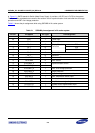
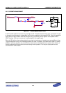
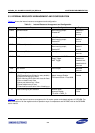
Figure 3-4 Fan and BUZ Workflow
Figure 3-4
shows the workflow of FAN and BUZ. FAN is always on as the IH cooker is generating heat. Even
when the device is powered off by manually setting or system protection, it is still on as long as the IGBT
temperature is higher than 55 ℃, in order to prevent the cooker from hot temperature damage.
Buzzer is mainly used for information indication. Besides the first beaming at power on, it only gives alarm when
some error lasts for 2sec or no pan is detected after trying 30 times