


S3F84B8_ALL-IN-ONE IH COOKER_AN_REV 0.00 2 HARDWARE IMPLEMENTATION
2-8
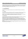
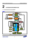
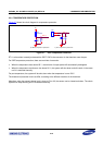
IH heating is the result of Eddy current caused by LC resonance. For a general cookware, the oscillation
frequency may vary from 20KHz to 30KHz. Since heating consumes energy, the IGBT should be periodically
turned on to allow the 220V power to compensate for the energy loss. Obviously, the longer it is turned on, the
more energy can be accumulated.
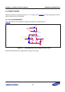
When the PWM output turns on the IGBT, electric energy is stored in the inductance and free LC oscillation is
started when the IGBT is turned off (as shown in Figure 2-3).
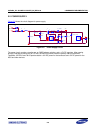
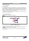
To make the system
work stably, consider the turn on frequency and turn on time of the IGBT. First, the turn on
frequency cannot destroy the LC oscillation, even though the IGBT on time will affect it a little bit. This means the
frequency of PWM output should be synchronized with the LC oscillation. It is realized by comparator0.
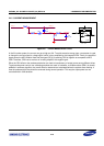
Second, considering the withstand voltage of IGBT, it is better to turn it on when the collector voltage is near ‘0’. It
can be realized by adjusting the divider resistors and enabling the delay trigger function of the IH PWM module. At
the same time, when proper delay time is set, thermal radiations will be largely reduced.
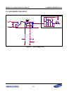
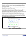
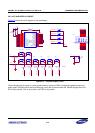
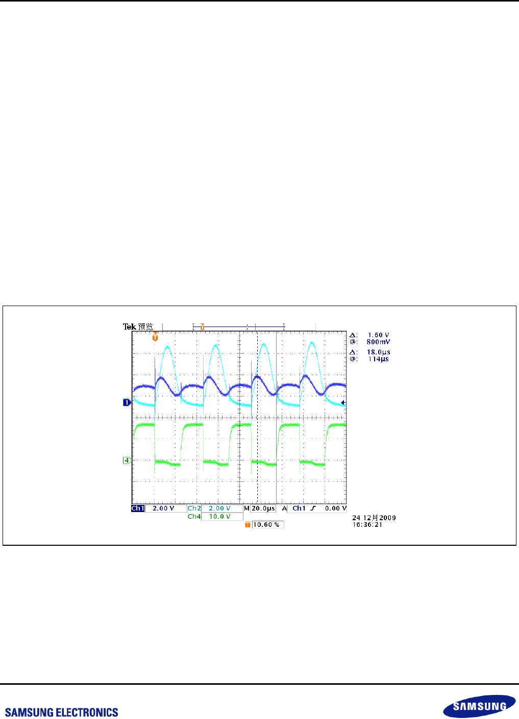
Figure6 shows the waveform of synchronization circuit. Light and dark blue waveforms show the inputs of
comparator0. The green waveform is measured at P0.4 (PWM). Additionally, the crossing point of the light and
dark blue waveforms trigger the rising of PWM output (High level at the base) which turns on the IGBT. The
duration of PWM’s outputting high is the result of software power control. When PWM output (green waveform)
returns to low level, the light and dark waveform presents free oscillation of the circuit, though the existence of the
IGBT diode makes the oscillation waveform not an ideal one.
Figure 2-4 Waveform of the Synchronization Circuit