


2
2 - 7
W-2WAY ECO-i SYSTEM
Outdoor Unit Repair Procedures
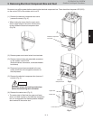
4. Backup Operation
<If the failed unit is the No. 1 outdoor unit (main unit)>
If the No. 1 unit (main unit) has failed, a different outdoor unit must be set as the No. 1 unit (main unit).
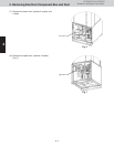
• Settings at the failed No. 1 outdoor unit
– No particular changes
– However, close all service valves (gas tube, liquid tube, balance tube) at the failed outdoor unit, and dis-
connect the wiring between the outdoor units.
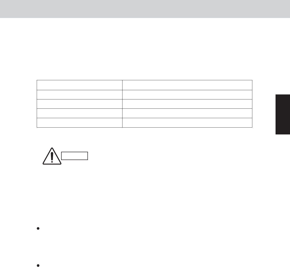
• Settings at No. 1 unit (main unit)
To this outdoor unit, connect the inter-unit communication line which was previously connected to the
No. 1 unit (main unit).
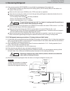
After recovery work is completed, wire the communication lines between
indoor and outdoor units again. If it not finished yet, an alarm is emitted
immediately.
• Settings at other outdoor units
No particular changes.
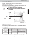
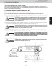
(2) Adjusting the refrigerant for backup operation
During backup operation, all of the service valves on the failed unit are closed. However, if a check of the
backup operating conditions shows that the level of gas is low, recover the refrigerant from the failed outdoor
unit. If the level of gas is too high, collect refrigerant at the failed outdoor unit.
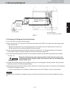
Recovering refrigerant
With the normal outdoor units operating, monitor the operating condition and open/close the gas tube ser-
vice valve on the failed outdoor unit where all the service valves were closed. In this way, recover refriger-
ant from the failed outdoor unit in order to adjust the amount of refrigerant in the system.
After adjusting the amount of refrigerant, close the gas tube valve at the failed outdoor unit.
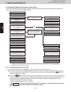
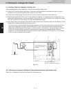
Collecting refrigerant in the failed outdoor unit
• Short-circuit the vacuum application pin (CN102) on the control PCB of the failed outdoor unit where the
service valves are closed, then turn the power ON. Also disconnect the wiring between the outdoor units.
• With the normal outdoor units operating, monitor the operating condition and open/close the liquid tube ser-
vice valve on the failed outdoor unit where all the service valves were closed. In this way, collect refrigerant
in the failed outdoor unit in order to adjust the amount of refrigerant in the system.
• After adjusting the amount of refrigerant, turn OFF the power at the failed outdoor unit, release the short-
circuit at the vacuum application pin, and close the liquid tube valve at the failed outdoor unit.
* Refrigerant recovery is not affected by the power status of the failed outdoor unit. However, collecting
refrigerant in the failed outdoor unit is affected by whether the power at that outdoor unit can be turned ON.
If the power cannot be turned ON, use a refrigerant recovery device and recover the refrigerant into a
recovery cylinder in order to adjust the amount of refrigerant in the system.
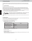
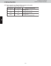
CAUTION
Switch on outdoor unit control PCB Action
System address (S003, S002) Make the same settings as on the failed No. 1 unit.
No. of indoor units (S005, S004) Make the same settings as on the failed No. 1 unit.
No. of outdoor units (S006) Subtract the number of failed units from the current setting.
Setting outdoor unit No. (S007) Change to “1.”