


2
2 - 10
5. Recovering Refrigerant
W-2WAY ECO-i SYSTEM
Outdoor Unit Repair Procedures
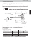
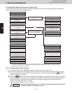
5-2. Refrigerant Recovery Procedures (Indoor Unit)
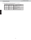
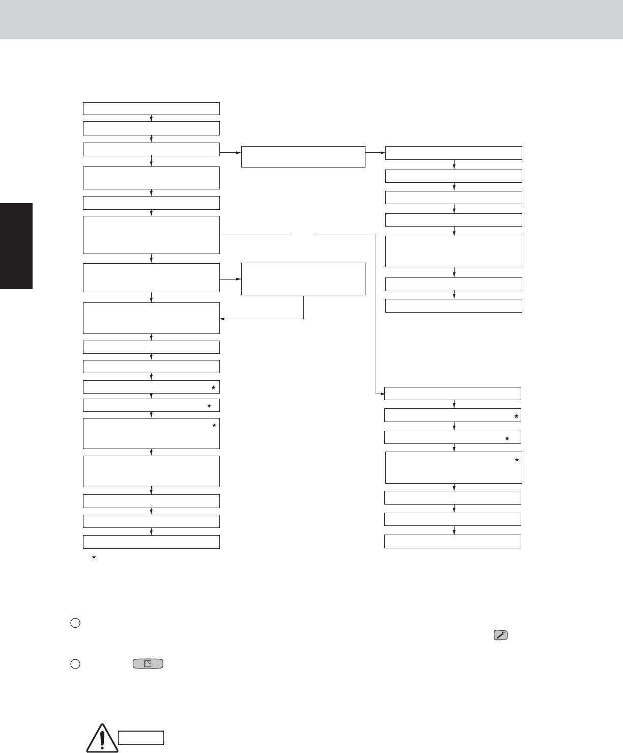
The flowchart below shows the refrigerant recovery procedures you must follow when replacing or repairing the
indoor unit due to trouble in the refrigerant circuit.
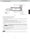
Service work performed on indoor units is done simultaneously using the service ports at the liquid (narrow tube) side
and the gas (wide tube) side ball valves. Refer to each section in the “Installation Instructions” on refrigerant charging,
leak checking, and evacuation procedures.
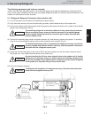
5-2-1. Cooling operation (for all units)
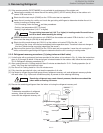
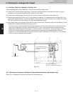
(1) If the remote controller (RCS-TM80BG) is used for maintenance of the outdoor unit
Connect the outdoor unit maintenance remote controller to the RC connector (CN006) (3P) (BLU) on any
one of the outdoor unit control PCBs. Then start a test run of all units. (Press and hold the (CHECK)
button for 4 seconds or longer.)
Press the (MODE) button and change to cooling operation and ensure that the cooling is performed.
Refer to the test run service manual for the detail of the outdoor maintenance remote controller operation.
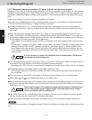
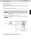
It may be possible to determine whether operation is cooling or heating by touching the gas tubing.
Cooling : low temperature (68 °F or lower)
Heating : high temperature (140 °F or higher)
The gas tubing becomes hot (140 °F or higher) in heating mode. Be careful so as
not to be burnt when touching the tubing.
CAUTION
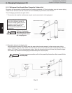
START
5-2-1. Cooling operation (for all units)
Ball valve is provided in the indoor unit
Turn off all equipment in system
Replace or repair faulty unit
Check for leakage in repaired unit
Evacuate air from repaired unit
Ready for operation
END
Charge refrigerant in repaired unit
(Amount of charge should equal that
recovered by refrigerant recovery unit)
Charge refrigerant in repaired unit H
(Amount of charge should equal that
recovered by refrigerant recovery unit)
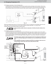
5-2-3. Refrigerant recovery
procedures (2)
Turn off all equipment in system
Other indoor units can operate normally
Replace or repair faulty unit
Check for leakage in repaired unit H
Evacuate air from repaired unit H
Open ball valve
Ready for normal operation
END
END
Ready for normal operation
Open the ball valve
Evacuate air in repaired unit H
Check for leakage in repaired unit H
Replace or repair faulty unit
Charge refrigerant in repaired unit H
(Amount of charge should equal that
recovered by refrigerant recovery unit)
Change controllable number of indoor
units (including changes in group
control and integrated-control settings)
5-2-2. Refrigerant recovery
procedures (1)
When replacing or repairing a faulty
unit, let other normal indoor units run
(excluding indoor unit where refrigerant
is recovered)
Modify power to permit turning off
power to refrigerant-recovered
indoor units independently
Power can independently be turned off
for indoor unit where refrigerant is
recovered
Change controllable number of indoor
units (including changes in group
control and integrated-control settings)
NO
NO
NO
YES
Fig.8
YES
YES
1
2