


82
9
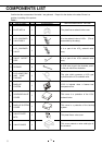
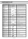
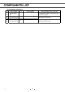
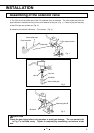
INSTALLATION
Installation of the door switch
1.
㩷
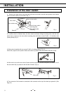
Spacer and a door switch mounting plate are fixed on the hole of the left side (upside) of the freezer
with two screws E (M5 x 16 pan head). (Fig. 1)
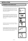
2. It confirms that an indicator lamp, the door switch and those wirings are being done, and the door
switch ass’y is fixed on the door switch mounting plate with three screws B (M4 x 10 stainless steel
(coating head)).(Fig. 2)
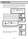
3. Strike plate is installed with two screws D (M5 x 10 stainless steel). (Fig. 3)
At this time, adjust it to the position where door switch is pushed under the condition that door closes.
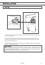
4. Wire cover is put on the rear side of freezer and the protection, and the wiring ass’y DS which it out of
the door switch ass’y is pasted on the left side of freezer. (Fig. 4)
5. The connector of the harness is connected to the connector on the top of the back-up system kit. (See
Page 12)
Fig. 2
Fig. 3
Fig. 4
Wire cover
㩷
Fig. 1
Door switch cover
Door switch
Screw B
Shim for door switch
mounting plate
Door switch plate
mounting
㪪㪺㫉㪼㫎㩷㪜㩷
Shim for door switch
Screw D