


84
11
INSTALLATION
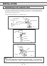
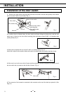
6. The sensor cover inside freezer chamber is removed, and the thermostat sensor part of the back-up
system is inserted into the hole under freezer temperature style sensor. The hole of the neighborhood of
the thermostat sensor part which inserted (A hole does not open an access port. Therefore, make a
hole in the plus driver.) into freezer inside and the rear side is stopped with silicon. Then, a thermostat
sensor is fixed on the sensor mounting plate by using the clip prepared in the sensor mounting plate in
advance. After that, gain a sensor cover inside in the former street. (Fig. 7)
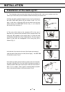
7. There is a access port which inserts the CO
2
valve outlet pipe of the
CO
2
solenoid into the lower corner hole of MDF-UBK. The CO
2
valve
outlet pipe is inserted in that, and a LCO
2
solenoid valve is fixed on
MDF-UBK with one screw A (M4 x 10 C It is tight.). (Fig. 8) The
mounting plate A is fixed with two screws A (M4 x 10 C is tight.). The
surroundings of the CO
2
valve outlet pipe which inserted into freezer
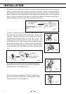
are blocked with silicon. (Fig. 9) The valve cover mounting plate is
fixed by using the screw which sticks in the freezer in advance. It gains
a valve cover after a CO
2
valve outlet pipe is bent in the bottom. (Fig.
10)
8. The wiring ass’y DS which it goes to out of the door switch ass’y
is passed through the nylon clip 6N, and MDF-UBK is stopped with
one screw A (M4 x 10 C It is tight.). (Fig. 11)
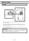
9. When all harness management is finished, a solenoid valve
cover is fixed with four screws B (M4 x 10 stainless steel (coating
head)) four places. (Fig. 12) (see page 12.)
Fig. 8
Fig. 9
Fig. 12
Fig. 11
Thermostat sensor
(A pipe is made a U
form.)
Sensor cover
䋨screw hole is
u
p
side䋩
screw
Fig. 7
Fig.10
Silicon
chamber
side
Valve outlet pipe
䋨Copper pipe䋩
It is blocked with
the silicone.