


KIT PART NO. (KIT 045) 344119
A WARNING:
• ALL RANGES CAN TIP
• INJURY COULD RESULT
• INSTALL ANTI-TIP DEVICE
PACKED WITH RANGE
• SEE INSTRUCTIONS
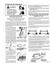
GAS RANGE STABILITY DEVICE
INSTALLATION INSTRUCTIONS
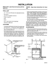
REMOVE ALL PARTS FROM THE PLASTIC BAG
ATTACHED TO THE BACK OF THE RANGE
AND SAVE PACKAGING TAPE.
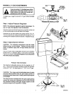
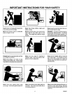
2) Fasten one end of the stability
chain to the floar or the wall with
the long screw and washer sup-
plied. See Ftg. 2. Make certain
the screw is going into the wall
plate at the base of the wall or one
of the studs in the wall. See Fig.
3. Whether you attach the chain
to the wall or floor, be certain that
the screw is in at least 3/4" thick-
ness of wood other than base-
board and that there are no elec-
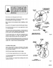
1) Before placing range in the counter, notice the Iocation of the
stability bracket which is already attached to the back of the range.
This location should work for r_ost instali_[;_,=s. H:_wew.r, it m_y
be more convenient to hook the stability chain to the unit when the
stability bracket is attached to the upper set of holes in the back of
the range. See Fig. 1.
BRACKE_
OPTIONA
LOCATION
CHAJ
BRACK
FACTORY
tricalwiresorplumbinginthearea =.OCATION Fig. 1 MAINEIACK
in which the screw could pene-
trate. Attach the stability chain in a location which will allow the
chain to be in line with the bracket side to side as much as possible
when attached _o the unit. Test to see if the chain is securely
fastened by tugging on the chain,
CHAIN
WASHER
AND
Fig. 2
Fig. 3
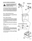
3) Temporarily attach the loose
end of the chain to the rear of the
countertop with the tape from the
packaging, See Fig. 4,
4) Placethe range inthe counter
cut out leaving just enough room
between the back of the range
and tile wall to reach the stability
bracket.
5) Hook the loose end of the
chain onto the bracket by slip-
ping the nearest link of the chain
Fig. 4
into the slot in the bracket (See Fig. 1), making sure the chain is
pulled as tight as possible and that there is no excess slack in the
chain after chain is attached to the bracket.
* Excess slack in the chain could allow the range to
tip over excessively.
6) Slide the range all the way back into the counter. Once the
range ispushed back in place, there will be a small amount of slack
in the chain. This is normal.
IMPORTANT INSTALLATION INSTRUCTIONS
FOR RANGES USED WITH COUNTERTOP
HEIGHTS UP TO 38"
The height of the range must be adjusted tothe countertop height.
For countertop heights greater than 37", additional measurements
may need to be taken as detailed below.
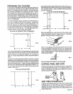
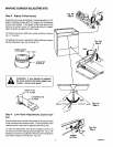
WRen the range isetevated to the maximum height, there isa Iarge
space between the bottom of the range and the floor, referred to as
the toe space. This may be visually objectionable. The legs should
not be extended any further than to provide a maximum of 3" toe
space. See Fig. 1.
Fig. 1
The range is designed to provide a minimum of 1" air gap at the
bottom of the range. See Fig. 2. (Example: When legs are screwed
all the way into the base rail.)
10
This gap is very important to the proper ventilation of the range and
must be maintained when treating the appearance of the toe space.
The following is a suggested method of making a filler for the toe
space when the legs are extended as mentioned before.
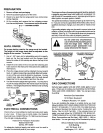
After the range is installed with the longer legs and isin position and
level, measu refrom the bottom of the bodyside to the floor. This will
bethe required height ofthe toe space filler. See Fig. 1, This height
may range from 2-1/16" to 3". Any height less than 2-1/16" may not
be visually objectionable and not need the filler.
B_.:,=,d',hefiiier as shown in Fig. 3. Make sure to provide the 3/4" gap
at the top and the 5/16" gap at the bottom. These gaps will provide
the proper ventilation as mentioned before.
If you wish to attach the filler to the floor Dr adjacent cabinets, use
screws or other removable fasteners, so that the range can be
readily removed if necessary.
GUSSETCORNERS
WITH _4"TO 1"
TRIANGULAR OR
SQUARESTOCK
3/4"
AS REQUIRED
OR AS REQUIRED
TO RECESS BEHIND
TOE A REA OF
ADJACENT CABINETS
USE 1/4" TO 1/2"
MATERIAL FINtSHED
TO MATCH TOE AREA
OF CABINETS
GINS113