


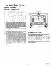
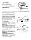
LIFT-UP COOKTOP
Toraise lhe cooktop so the area underneath can be cleaned,
grasp the cooktop at the front and lift up.
The range has a support to hold the cooktop while cleaning.
Raise the support as shown in the illustration.
Porcelain enamel can chip if dropped. Handle porcelain
enameled cooktops carefully.
REMOVABLE COOKTOP BURNERS
The cooktop burners on your range may be removed for
cleaning Be sure all cooktop knobs are turned to OFF
and burners are cool, then remove or raise the cooktop.
Some models have two types of burners. One type of burner
has a solid top and is used at the two rear cooktop positions
and at the left front cooktop position of some models.
The second type of burner iscone-shaped and has a circular
opening through the center of the burner head. This 12,000
13TUburner is used at the right front cooktop position or at
both front cooktop positions of some models.
De not try to use the burners in any other position. Damage
toyour range may result ifthe smaller burners are used inthe
12,000 BTU burner positions.
If shipping screws were not removed from the burner when
the range was installed, do so now (see your Installation
Guide for instructions). These screws may be discarded.
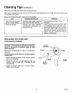
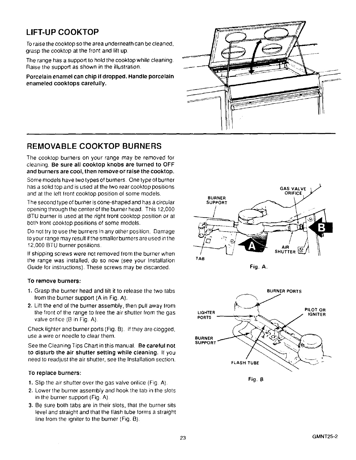
To remove burners:
1. Grasp the burner head and tilt it to release the two tabs
from the burner support (A in Fig. A).
2. Lift the end of the burner assembly, then pull away from
the front of the range to free the air shutter from the gas
valve orifice (B in Fig. A).
Check lighter and burner ports (Fig. B). If they are clogged,
use a wire or needle to clear them.
See the Cleaning Tips Chart in this manual. Be careful not
to disturb the air shutter setting while cleaning. If you
need to readjust the air shutter, see the Installation section.
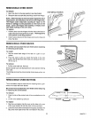
To replace burners:
1. Slip the air shutter over the gas valve orilice (Fig A)
2. Lower the burner assembly and hook the tab in the slots
in the burner suppod (Fig. A)
3. Be sure bolh tabs are in their slots, that the burner sits
level and straight and that the flash tube forms a straight
line from the igniler to the burner (Fig. B)
BURNER
SUPPORT
TAB
Fig. A.
LIGHTER
PORTS
FLASH TUBE
GAS VALVE
ORIFICE
AIR
SHUTTEF
BURNER PORTS
PILOT OR
Fig. B
23 GMNT25-2