


R-210A
13
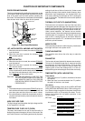
COMPONENT REPLACEMENT AND ADJUSTMENT PROCEDURE
WARNING: Avoid possible exposure to microwave energy. Please follow the instructions
below before operating the oven.
1. Disconnect oven from power supply.
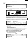
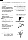
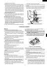
2. Make sure that a definite” click” can be heard when the
microwave oven door is unlatched. (Hold the door in a
closed position with one hand, then push the door open
button with the other, this causes the latch leads to rise,
it is then possible to hear a “click’ as the door switches
operate.)
3. Visually check the door and cavity face plate for dam-
age (dents, cracks, signs of arcing etc.).
Carry out any remedial work that is necessary before
operating the oven.
Do not operate the oven if any of the following conditions
exist;
1. Door does not close firmly.
2. Door hinge, support or latch hook is damaged.
3. The door gasket or seal or damaged.
4. The door is bent or warped.
5. There are defective parts in the door interlock system.
6. There are defective parts in the microwave generating
and transmission assembly.
7. There is visible damage to the oven.
Do not operate the oven:
1. Without the RF gasket (Magnetron).
2. If the wave guide or oven cavity are not intact.
3. If the door is not closed.
4. If the outer case (cabinet) is not fitted.
Please refer to ‘OVEN PARTS, CABINET PARTS, CONTROL PANEL PARTS, DOOR PARTS’, when carrying out any
of the following removal procedures:
WARNING FOR WIRING
To prevent an electric shock, take the following
manners.
1. Before wiring,
1) Disconnect the power supply.
2) Open the door and wedge the door open.
3) Discharge the high voltage capacitor and wait for
60 seconds.
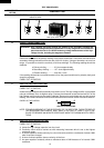
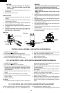
2. Don't let the wire leads touch to the following parts;
1) High voltage parts:
Magnetron, High voltage transformer, High volt-
age capacitor and High voltage rectifier assem-
bly.
2) Hot parts:
Oven lamp, Magnetron, High voltage transformer
and Oven cavity.
3) Sharp edge:
Bottom plate, Oven cavity, Weveguide flange,
Chassis support and other metallic plate.
4) Movable parts (to prevent a fault)
Fan blade, Fan motor, Switch, Switch lever, Open
button.
3. Do not catch the wire leads in the outer case cabinet.
4. Insert the positive lock connector certainly until its pin
is locked. And make sure that the wire leads should
not come off even if the wire leads is pulled.
5. To prevent an error function, connect the wire leads
correctly, referring to the Pictorial Diagram.
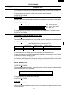
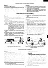
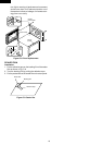
To remove the outer case proceed as follows.
1. Disconnect oven from power supply.
2. Open the oven door and wedge it open.
3. Remove the screws from rear and along the side edge
of case.
4. Slide the entire case back about 3cm to free it from
retaining clips on the cavity face plate.
5. Lift the entire case from the oven.
6. Discharge the H.V. capacitor before carrying out any
further work.
7. Do not operate the oven with the outer case removed.
N.B.; Step 1, 2 and 6 form the basis of the 3D checks.
CAUTION: DISCHARGE HIGH VOLTAGE CAPACITOR
BEFORE TOUCHING ANY OVEN COMPO-
NENT OR WIRING.
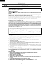
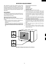
OUTER CASE REMOVAL
1. CARRY OUT 3D CHECKS.
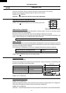
2. Disconnect the wire leads (main wire harness and H.V.
fuse) from power transformer.
3. Disconnect the H.V. wire of the H.V. rectifier assembly
from magnetron.
4. Disconnect the wire leads from the noise filter.
5. Remove the one (1) screw holding the capacitor holder
to the oven cavity back plate.
6. Disconnect the filament lead of power transformer from
the magnetron.
7. Disconnect the lead of the power transformer from high
voltage capacitor.
8. Remove the two (2) screws holding the transformer to
bottom plate.
9. Remove the transformer.
POWER TRANSFORMER REMOVAL