


R-210A
15
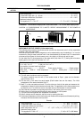
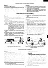
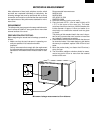
POWER SUPPLY CORD REPLACEMENT
Removal
1. CARRY OUT 3D CHECKS.
2. Disconnect the wire leads from the power supply cord.
3. Remove the one (1) screw holding the power supply
cord to the oven cavity back plate.
4. Remove the power supply cord from the oven cavity
back plate.
Re-install
1.
Insert the power supply cord into the oven cavity back plate.
2. Secure the one (1) screw holding the power supply
cord to the oven cavity back plate..
3. Connect the white and black wires of the main wire
harness into the terminal of the power supply cord,
referring to the Pictorial Diagram.
TURNTABLE MOTOR REPLACEMENT
Removal
1. Disconnect the oven from the power supply.
2. Remove the turntable and turntable support from the
oven cavity.
3. Turn the oven over.
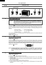
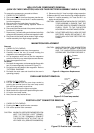
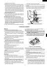
4. Cut the four (4) bridges holding the turntable motor
cover to the bottom plate with the cutting pliers as
shown in Figure C-4.
CAUTION: DO NOT DROP THE TURNTABLE MOTOR
COVER INTO THE OVEN AFTER CUTTING
THE BRIDGES. BECAUSE IT WILL DAM-
AGE THE WIRE LEADS OF THE MOTOR
AND IT IS DIFFICULT TO REMOVE IT OUT
OF THE OVEN.
5. Remove the turntable motor cover from the bottom
plate.
6. Disconnect the wire leads from the turntable motor.
7. Remove the single (1) screw holding the turntable
motor to the oven cavity.
8. Remove the turntable motor from the oven cavity.
9. Remove the O-ring and washer from the turntable
motor.
10.Now, the turntable motor is free.
Re-install
1. Remove the any sharp edges on the turntable motor
cover and the bottom plate with the cutting pliers.
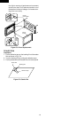
2. Re-install the O-ring.
3. Apply the grease (Shinetsu silicone grease G-420 of
Sinetsu Chemical Co. Ltd. or Toray Silicone grease
SH-14 of Toray Silicone Co., Ltd.) to the O-ring and the
base of the turntable motor shaft as shown in Figure C-
6.
4. Re-install the turntable motor with the O-ring and
washer to the oven cavity with the single (1) screw.
5. Re-connect the wire leads to the turntable motor.
6. Insert the tab of the turntable motor cover into the hole
of the bottom plate as shown in Figure C-4.
7. Re-install the turntable motor cover to the bottom plate
with one (1) screw XHTSD40P08RV0 or
XFPSD40P08K00 as shown in Figure C-4.
Cutting pliers
Bridges
Bridges
Turntable motor
cover
XHTSD40P08RV0
or
XFPSD40P08K00
Tab
Hole
Bottom plate
Screw:
Washer
O-ring
Base of turntable
motor shaft
Turntable motor
O-ring
Washer
Apply grease here
Figure C-4. Turntable Motor Cover
Figure C-5. Washer and O-ring Installation and
Grease Applying.
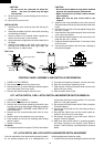
REMOVAL
1. CARRY OUT 3D CHECKS.
2. Disconnect the wire leads from the fan motor.
3. Remove the one (1) screw holding the chassis support
to the oven cavity front plate.
4. Remove the chassis support .
5. Release the filament lead of the power transformer and
the H.V. wire from the fan duct.
6. Remove the one (1) screw holding the fan duct to the
waveguide flange.
7. Release the fan motor assembly from the oven cavity.
8. Remove the fan blade from the fan motor shaft accord-
ing to the following procedure.
1) Hold the edge of the rotor of the fan motor by using
a pair of groove joint pliers.
CAUTION:
• Make sure that any pieces do not enter the gap
between the rotor and the stator of the fan
motor. Because the rotor is easy to be shaven
by pliers and metal pieces may be produced.
• Do not touch the pliers to the coil of the fan
motor because the coil may be cut or injured.
• Do not transform the bracket by touching with
the pliers.
2) Remove the fan blade assembly from the shaft of
the fan motor by pulling and rotating the fan blade
with your hand.
3) Now, the fan blade will be free.
FAN MOTOR REPLACEMENT