


R-210A
4
OPERATION SEQUENCE
7-1. When the oven door is opened during or after the
cycle of a cooking program, the 1st latch switch and
2nd latch switch must open their (COM-NO) contacts
first. After that the contacts (COM-NC) of the monitor
switch can be closed.
7-2. When the oven door is closed. The contacts (COM-
NC) of the monitor switch must be opened and the
contacts (COM-NO) of the 2nd latch switch and the
1st latch switch must be closed.
7-3. When the oven door is opened and the (COM-NO)
contacts of the 1st latch switch and the contacts
(COM-NO) of the 2nd latch switch remain closed, the
fuse 13A will blow, the monitor switch is closed and a
short circuit is caused.
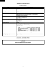
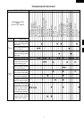
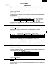
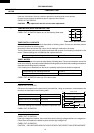
MEDIUM HIGH, MEDIUM, MEDIUM LOW, LOW
COOKING
When the microwave oven is preset for variable cooking
power, the rated voltage is supplied to the power trans-
former intermittently within a 30-second time base through
the vari switch. The following levels of microwave power
are given.
HIGH
30 sec. ON
MEDIUM HIGH Approx. 70%
Approx. 100%
23.2 sec. ON 6.8 sec. OFF
13.5 sec. OFF
20.2 sec. OFF
MEDIUM Approx. 50%
16.5 sec. ON
MEDIUM LOW Approx. 30%
9.8 sec. ON
25 sec. OFF
LOW Approx. 10%
5.0 sec. ON
Note: The ON/OFF time ratio does not exactly corre-
spond to the percentage of microwave power,
because approx. 2 seconds are needed for heat-
ing up the magnetron filament.
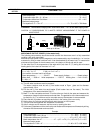
OFF CONDITION
1. When the timer knob is at " 0 ", the oven is OFF
condition.
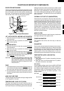
2. Closing the oven door activates the 1st latch switch, the
2nd latch switch and monitor switch.
IMPORTANT:
When the oven door is closed, the contacts COM-NC of
the monitor switch must be open.
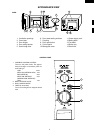
Figure O-1 on page 20
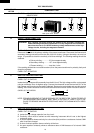
MICROWAVE COOKING CONDITION
HIGH COOKING
Set the variable cooking control to HIGH and then set the
timer.
Function sequence
Figure O-2 on page 20
1. Following components are energized.
Power transformer H.V. capacitor Timer motor
Magnetron H.V. rectifier Fan motor
H. V. fuse Turntable motor Oven lamp
2. Rated voltage is supplied to the primary winding of the
power transformer. The voltage is converted to about
3.3 volts A.C. output on the filament winding and high
voltage of approximately 2000 volts A.C. on the sec-
ondary winding.
3. The filament winding voltage (3.3 volts) heats the
magnetron filament and the high voltage (2000 volts) is
sent to the voltagedoubling circuit, where it is doubled
to negative voltage of approximately 4000 volts D.C..
4. The 2450 MHz microwave energy produced in the
magnetron generates a wave length of 12.24 cm. This
energy is channelled through the waveguide (transport
channel) into the oven cavity, where the food is placed
to be cooked.
5. When the cooking time is up, the timer returns to "0",
the bell rings and the contacts of the timer are opened.
Then following components are turned off.
Power transformer Magnetron Timer motor
Turntable motor H.V. capacitor Fan motor
H. V. fuse H.V. rectifier Oven lamp
6. When the oven door is opened during a cooking cycle,
the switches come to the following positions and they
are common to the other cooking conditions too.
Switch Contact Condition
During Oven Door
Cooking Open(No cooking)
1st latch Switch COM-NO Closed Opened
Monitor Switch COM-NC Opened Closed
2nd latch switch COM-NO Closed Opened
The circuit to the power transformer, turntable motor,
timer motor, fan motor and oven lamp are cut off when
the COM-NO contacts of the 2nd latch switch and 1st
latch switch are made open. The timer stops to indicate
how much cooking time remains.
7. MONITOR SWITCH CIRCUIT
The monitor switch is mechanically controlled by the
oven door, and monitors the operation of the 1st latch
switch and 2nd latch switch.
SETTING