


R-210A
14
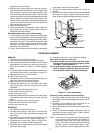
HIGH VOLTAGE COMPONENTS REMOVAL
(HIGH VOLTAGE CAPACITOR, HIGH VOLTAGE RECTIFIER ASSEMBLY AND H.V. FUSE)
To remove the components, proceed as follows.
1. CARRY OUT 3D CHECKS.
2. Disconnect the H.V. fuse from the power transformer.
3. Disconnect the H.V. wire of the H.V. rectifier assembly
from the magnetron.
4. Disconnect the wire leads from the noise filter.
5. Remove one (1) screw holding capacitor holder to
oven cavity back plate.
6. Disconnect the filament lead of the power transformer
from the H.V. capacitor.
7.
Remove one (1) screw holding earth side terminal of high
voltage rectifier assembly, and remove capacitor holder.
8. Disconnect all the leads and terminals of high voltage
rectifier assembly from high voltage capacitor.
9. Disconnect the H.V. fuse from high voltage capacitor.
10.
Remove the HVC cover from the high voltage capacitor.
11.Now H.V. rectifier assembly, H.V. fuse and H.V. ca-
pacitor should be free.
CAUTION: WHEN REPLACING HIGH VOLTAGE REC-
TIFIER ASSEMBLY, ENSURE THAT THE
CATHODE (EARTH) CONNECTION IS SE-
CURELY FIXED TO THE CAPACITOR
HOLDER WITH AN EARTHING SCREW.
CAUTION: DO NOT REPLACE ONLY HIGH VOLTAGE
RECTIFIER. WHEN REPLACING IT, RE-
PLACE HIGH VOLTAGE RECTIFIER AS-
SEMBLY.
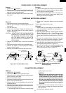
1. CARRY OUT 3D CHECKS.
2. Pull the wire leads from the oven lamp socket by
pushing the terminal hole of the oven lamp socket
with the flat type small screw driver.
3. Tear the cushion from the light mount plate.
4. Bend the tab of the light mount plate holding the oven.
5. Lift up the oven lamp socket.
6. Now, the oven lamp socket is free.
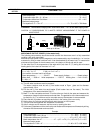
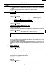
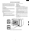
OVEN LAMP SOCKET REMOVAL
Figure C-2. Oven lamp socket
POSITIVE LOCK
®
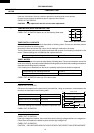
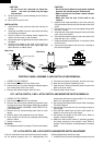
CONNECTOR REMOVAL
1. CARRY OUT 3D CHECKS.
2. Pushing the lever of positive lock
®
connector.
3. Pull out the positive lock
®
connector.
CAUTION: WHEN YOU (SERVICE ENGINEERS) CON-
NECT THE POSITIVE LOCK
®
CONNEC-
TORS TO THE TERMINALS, CONNECT
THE POSITIVE LOCK
®
SO THAT THE LE-
VER FACE YOU (SERVICE ENGINEERS).
Terminal
Push
Pull down
1
2
Lever
Positive lock®
connector
Figure C-3 Positive lock
®
connector
Removal
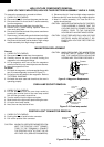
1. CARRY OUT 3D CHECKS.
2. Disconnect the wire leads from the magnetron.
3. Carefully remove the two (2) screws holding the
magnetron to the waveguide flange.
4. Lift up magnetron with care so that the magnetron
antenna is not hit by any metal object around antenna.
5. Now, the magnetron is free.
Re-install
1. Re-install the magnetron to the waveguide flange with
two (2) screws diagonally as shown in Figure C-1.
2. Re-connect the wire leads to the magnetron. Refer to
"PICTORIAL DIAGRAM".
3. Re-install the outer case and check that the oven is
operating properly.
CAUTION: WHEN REPLACING THE MAGNETRON,
BE SURE THE R.F. GASKET IS IN PLACE
AND THE MAGNETRON MOUNTING
SCREWS ARE TIGHTENED SECURELY.
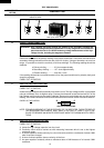
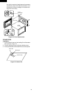
MAGNETRON REPLACEMENT
Figure C-1. Magnetron Replacement
Screws
Magnetron
Wavegiude
Flange
Oven lamp
socket
Terminal
Wire lead
Terminal hole
Flate type small
screw driver