


R-210A
5
FUNCTION OF IMPORTANT COMPONENTS
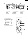
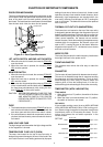
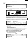
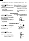
DOOR OPEN MECHANISM
The door can be opened by pushing the open button on the
control panel. When the open button is pushed, the switch
lever on the latch hook is moved upward, operating the
latch head. The latch head is moved upward, and released
from the latch hook. Now, the door can be opened.
LATCH HOOK
LATCH
HEADS
DOOR
MONITOR
SWITCH
1ST. LATCH
SWITCH
2ND. LATCH
SWITCH
SWITCH LEVER
Figure D-1. Door Open Mechanism
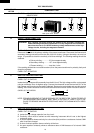
1ST. LATCH SWITCH AND 2ND. LATCH SWITCH
1. When the oven door is closed, the contacts (COM-NO)
must be closed.
2. When the oven door is opened, the contacts (COM-
NO) must be opened.
MONITOR SWITCH
1. When the oven door is closed, the contacts (COM-NC)
must be opened.
2. When the oven door is opened, the contacts (COM-
NC) must be closed.
3. If the oven door is opened and the contacts (COM-NO)
of the 1st latch switch and 2nd latch switch fail to open,
the fuse blows simultaneously with closing the con-
tacts (COM-NC) of the monitor switch.
CAUTION: BEFORE REPLACING A FUSE TEST THE
1ST LATCH SWITCH, 2ND LATCH SWITCH
AND MONITOR SWITCH FOR PROPER
OPERATION. (REFER TO CHAPTER "TEST
PROCEDURE".)
FUSE
1.
The fuse blows when the contacts (COM-NO) of the 1st
latch switch and 2nd latch switch remain closed with the
oven door open and when the monitor switch closes.
2. If the wire harness or electrical components are short-
circuited, the fuse blows to prevent an electric shock of
fire hazard.
HIGH VOLTAGE FUSE
The high voltage fuse blows when the high voltage rectifier
or the magnetron is shorted.
TEMPERATURE FUSE 120˚C (OVEN)
The temp. fuse located on the top of the oven cavity is
designed to prevent damage to the oven if the foods in the
oven catch fire due to over heating produced by improper
setting of cook time or failure of control unit. Under normal
operation, the temp. fuse remains closed. However, when
abnormally high temperatures are reached within the
oven cavity, the temp. fuse will open at 120˚C, causing the
oven to shut down. The defective fuse must be replaced
with a new one.
THERMAL CUT-OUT 95˚C (MAGNETRON )
The thermal cut-out located on the top of the oven cavity
is designed to prevent damage to the magnetron if an over
heated condition develops in the tube due to cooling fan
failure, obstructed air guide, dirty or blocked air intake, etc.
Under normal operation, the thermal cut-out remains
closed. However, when abnormally high temperatures are
reached within the magnetron, the thermal cut-out will
open at 95˚C, causing the oven to shut down. When the
magnetron has cooled to 75˚, the thermal cut-out closes
and cook cycle will resume.
NOISE FILTER
The noise filter prevents the radio frequency interference
that might flow back in the power circuit.
TURNTABLE MOTOR
The turntable motor drives the roller stay to rotate the
turntable.
FAN MOTOR
The fan motor drives a blade which draws external cool air.
This cool air is directed through the air vanes surrounding
the magnetron and cools the magnetron. This air is chan-
nelled through the oven cavity to remove steam and
vapours given off from the heating foods. It is then ex-
hausted through the exhausting air vents at the oven cavity.
TIMER MOTOR (WITH VARI-SWITCH)
Timer switch
1. When the timer is at "0" position, the switch of the timer
are opened.
2. When the timer is turned clockwise from "0" position,
the switch of the timer are closed.
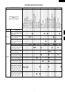
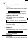
Vari-switch
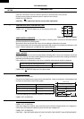
If the variable cooking control is set at HIGH, MEDIUM
HIGH, MEDIUM, MEDIUM LOW or LOW cooking posi-
tion, Rated voltage is supplied to the power transformer
intermittently within a 30 seconds time base. The fol-
lowing chart shows the vari-switch operation in the
various modes.
HIGH
30 sec. ON
MEDIUM HIGH Approx. 70%
Approx. 100%
23.2 sec. ON 6.8 sec. OFF
13.5 sec. OFF
20.2 sec. OFF
MEDIUM Approx. 50%
16.5 sec. ON
MEDIUM LOW Approx. 30%
9.8 sec. ON
25 sec. OFF
LOW Approx. 10%
5.0 sec. ON
SETTING