


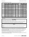

500 SERIES RESTAURANT RANGES SPECIFICATIONS
OWNER’S MANUAL 1188716 (02/07) PAGE 7 OF 44
In case of unsatisfactory performance on any appliance, check the appliance with the exhaust fan in the OFF position.
Do this only long enough to check equipment performance. Then turn hood back on and let it run to remove any
exhaust that may have accumulated during the test.
GAS SUPPLY
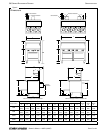
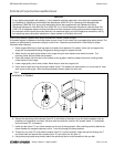
A 3/4" female NPT gas connection is located on the rear of the range (see Figure 2).
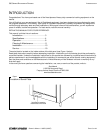
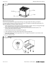
The serial plate is located on the right side of the range (See
Figure 1). The serial plate indicates the type of gas the
range is equipped to burn. All Southbend equipment is adjusted at the factory. Check type of gas on serial plate.
These models are design-certified for operation on natural or propane gases. For natural gas, the regulator is set to 4"
W.C. (0.99 kPa). For propane gas, it is set to 10" W.C. (2.48 kPa).
If applicable, the vent line from the gas appliance pressure regulator shall be installed to the outdoors in accordance
with local codes, or in the absence of local codes, with the applicable national codes.
This appliance should be connected ONLY to the type of gas for which it is equipped.
An adequate gas supply is imperative. Undersized or low pressure lines will restrict the volume of gas required for
satisfactory performance. Fluctuations of more than 25% on natural gas or 10% on propane gas will create problems
and affect burner operating characteristics. A 1/8" pressure tap is located on the manifold to measure the manifold
pressure.
An adequate gas supply line to the range should be no smaller than the inside diameter of the pipe from the range to
which it is connected.
Purge the supply line to clean out dust, dirt, or other foreign matter before connecting the line to the range.
All pipe joints and connections must be tested thoroughly for gas leaks. Use only soapy water for testing on all gases.
NEVER use an open flame to check for gas leaks. All connections must be checked for leaks after the range has
been put into operation. Test pressure should not exceed 14" W.C. (3.47 kPa).
ELECTRICAL REQUIREMENTS
Ranges with a convection oven require connection to a supply of electricity. The appliance, when installed, must be
electrically grounded in accordance with local codes, or in the absence of local codes, with the applicable national
codes. An electrical diagram is located on the rear of the range, near the motor.
Usually the range is furnished with one or two power cords (one for each oven), each with a standard 115V, 60Hz,
single-phase prong plug. Total maximum power for 115V units is 4.8 amperes.
The range can be ordered to operate on 208V 60Hz 1-phase or 3-phase current, in which case the electric power
supply must be wired to one or two junction boxes (one for each oven), each with a terminal block on the rear of the
range. Total maximum power for 208V units is 2.6 amperes.