


3
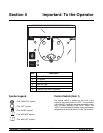
Models 382/RC25 To the Installer
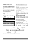
Note: 5/8” individual line lengths are not to exceed 75 ft. (22.8 m) maximum length each.
Total line length is not to exceed 150 ft. (45.7 m). 5/8” line + 5/8” line + 3/4” line = 150 ft. or less.
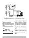
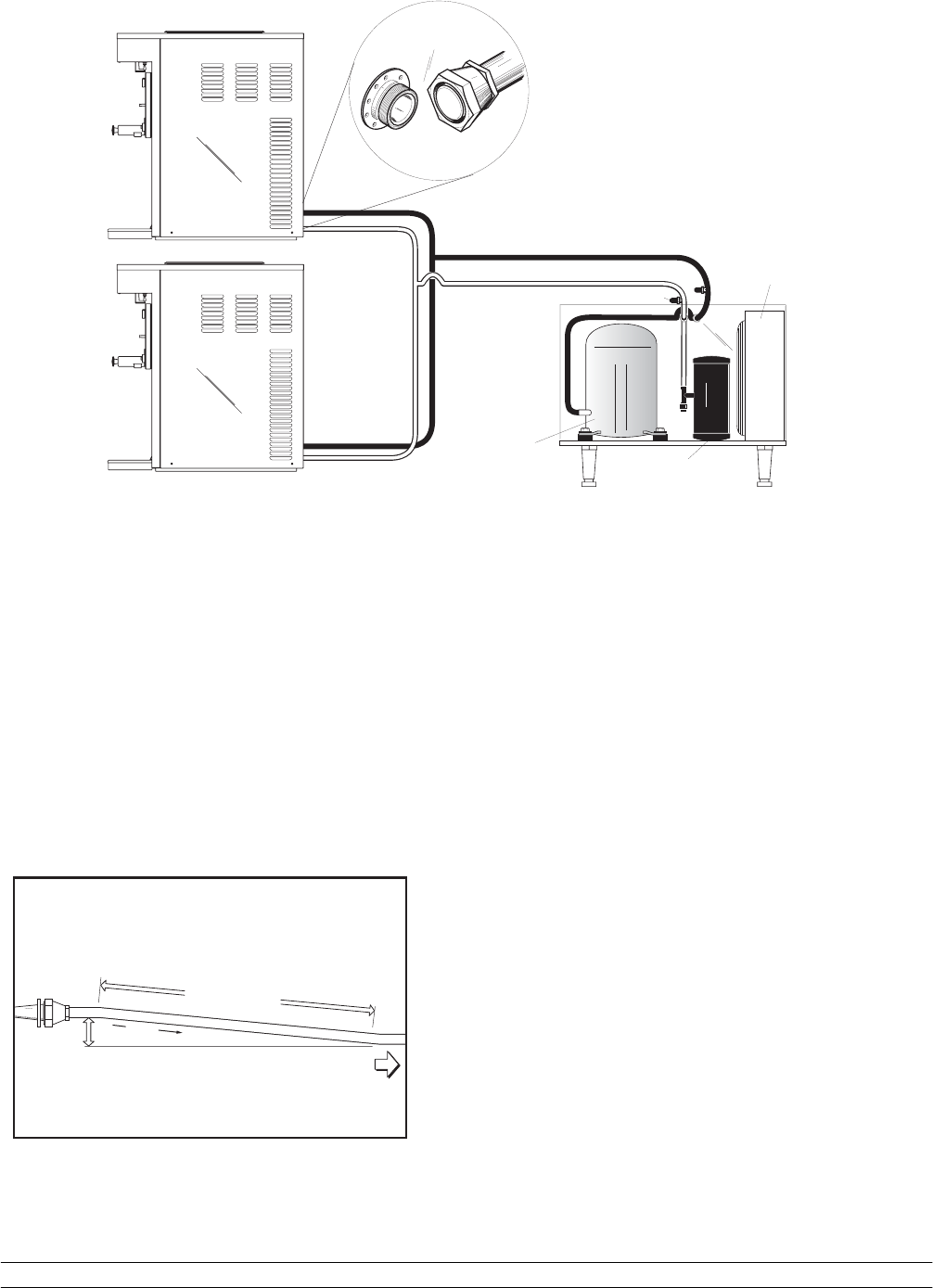
Figure 2
Compressor
Condenser
Liquid Refrigerant
Reciever
CONDENSING UNIT
Access Valve
DISPENSER UNIT
382
DISPENSER UNIT
382
Installation
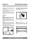
Step 1
Install refrigeration lines from the dispenser to the
condensing unit. Do not create oil traps.
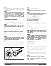
Note: For proper oil return, installation of horizontal
suction lines are to be sloped downward in the
direction of the condensing unit. The slope must be a
minimum 1/4” (6.4 mm) angle per 10 ft. (30.48 mm) of
line length.
FROM
DISPENSER
TO CONDENSER
¼" (.64 cm)
FLOW
10'-0"
(3.048 m)
Figure 3
Normally, any straight run of tubing must be supported
near each end of the run. Long runs require additional
supports. As a guide, 3/8” to 3/4” copper should be
supported every 5 ft. (1.5 m). When changing
directions, no corner should be left unsupported.
Supports should be placed a maximum of 2 ft. (.61 m)
in each direction from the corner . If soft copper tube is
used, make sure it is not kinked or flattened. If hard
drawn copper tubing is used, use only long radius
elbows.
Step 2
Braze the supplied quick connect/disconnect
couplings on the dispenser end of the r efrigeration
lines. Couplings are supplied with the dispenser.
Step 3
Braze the quick c onnect/disconnect couplings and
access tees on the condensing unit end of the
refrigeration lines. C ouplings and access tees ar e
supplied with the unit.
Note: Wrap a wet cloth around the brass coupling
bodies to prevent heat damage to the seal.
Step 4
Test the field constructed lines for leaks.