


11
Model 390 Operating Procedures
140804
Step 5
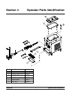
Install the freezer door. P lace the front end of the baffle
into thehole in thecent er of the door. Position the door
onto the four studs on the front of the freezing cylinder
and push the door into place. Ins tall the four
handscrews ont o the studs and tighten them equally in
a criss- cross pattern to ins ure the door is snug. DO
NOT over- tighten the handscrews.
Note: If the freezer door does not go into place easily,
position open end of beater assembly in the 11 o’clock
position.
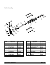
Step 6
Rotatethe baffle assem bly so the hole in theend of the
shaft is vertical. Insert the bafflearmbetween thedraw
valve spout supports and into the hole in the baffle
assembly.
Note: During operation, the baffle arm rests on the
spout support.
Step 7
Install the rear drip pan. Slide the long drip pan intothe
hole in the front panel.
Step 8
Install the front drip tray and the splash shield under
the door spout.
Step 9
Lay the hopper gasket and feed tube in the bottom of
the mix hopper.
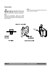
Sanitizing
Step 1
Prepare an approved 100 PPM sanitizing solution
(examples: 2- 1/2 gal. [9.5 liter s] of Kay- 5R or 2
gal. [7.6 liter s] of Stera- SheenR). USE WARM
W ATE R AND FOLLOW THE MANUFACTURER’S
SPECIFICATIONS.
Step 2
Pour the sanitizing s olution into the hopper and allow
it to flow into the freezing cylinder .
Step 3
While the solut ion is flowing into the freez ing cylinder ,
brush clean the mix hopper, m ix inlet hole, feed tube
and mix level sensing probes.
Step 4
Place the control switc h in the “WASH” position. This
will cause the sanitizing solution in the freezing
cylinder to be agitat ed. Allow the solution to agitate for
five minutes.
Step 5
Place an empty pail beneath the door spout and move
the draw handle to the right. Draw off all the sanitiz ing
solution. When the sanit izer st ops flowing from the
door spout, move the draw handle to the left and place
the control switch in the “OFF” posit ion.
Step 6
With sanitiz ed hands, assemble the hopper gasket
around the top edge of the mix hopper. Stand the feed
tube in the corner of the hopper .
Priming
Note: If your freez er is equipped with the Remote
Continuous Fill System, replace the following Priming
instruc tions with the information on page 9.
Step 1
With a pail beneath t he door spout, move the draw
handle to the right. Fill the hopper with FRE SH slush
product and allow it to flow into the freezing cylinder.
This will force out any r emaining s anitizing solution.
When full st rength mix is flowing from the door spout,
move the draw handle to the left.
Step 2
When the slush product has stopped bubbling down
into the freezing cylinder, install the feed tubein themix
inlet hole.
Step 3
Place the control switch in the “AUTO” position. To
begin ref rigeration, raise the rod resting on top of the
valve handle pin. When the unit cycles off, the product
will be at serving viscosity.
Step 4
Place the hopper c over into position.