


32
Model C712Operating Procedures
080908
Disassembly
MAKE SURE THE POWER SWITCH IS IN
THE “OFF” POSITION! Failure to follow this
instruction may result in severe personal injury from
hazardous moving parts.
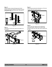
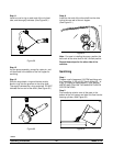
Step 1
Remove the handscrews, freezer door, beater and
scraper blades, and drive shaft with drive shaft seal
from the freezing cylinder.
Step 2
Remove the scraper blade clips from the scraper
blades.
Step 3
Remove the drive shaft seal from each drive shaft.
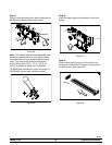
Step 4
From each pump cylinder, remove the retaining pin,
mix inlet adaptor, valve cap, pump gasket, and the
piston. Remove the o-ring from the piston and valve
cap.
Step 5
Remove the freezer door gaskets, front bearings,
pivot pin, draw handles, draw valves, prime plugs,
and design caps. Remove the o-rings from the draw
valves.
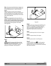
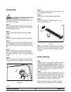
Step 6
Remove the pump drive shafts from the drive hubs
in the rear wall of the mix hoppers. (See Figure 66.)
Figure 66
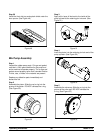
Step 7
Remove the two small o-rings and one large o-ring
from each pump drive shaft.
Step 8
Remove the front drip tray and splash shield.
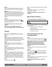
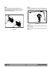
Step 9
Remove all drip pans. Take them to the sink for
cleaning. (See Figure 67.)
Figure 67
Note: If the drip pans are filled with an excessive
amount of mix, it is an indication that the drive shaft
seal(s), or o-ring(s) should be replaced or properly
lubricated.
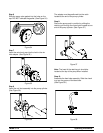
Brush Cleaning
Step 1
Prepare a sink with an approved 100 PPM cleaning/
sanitizing solution (examples: Kay-5® or Stera-
Sheen®). USE WARM WATER AND FOLLOW THE
MANUFACTURER'S SPECIFICATIONS. Make sure
all brushes provided with the freezer are available
for brush cleaning.
Step 2
Thoroughly brush clean all disassembled parts in the
cleaning solution, making sure all lubricant and mix
film is removed. Be sure to brush all surfaces and
holes, especially the holes in the pump components
and the draw valve holes in the freezer door.
Rinse all parts with clean, warm water. Place the
parts on a clean, dry surface to air dry overnight.