


3
Models RD30/RC25 To the In staller
120611
Refrigerant
In consideration of our environment, Taylor
proudly u ses only earth friendly H FC refrigerants. The
HFC refrigerant used in this unit is R404A. This
refrigerant is generally considered non-toxic and
non-flammable, with an Ozone Depleting Potential
(ODP) of zero (0).
However , any gas under pressure is potentially
hazardous and must be handled with c aution. NEVER
fill any refrigerant cylinder completely with liquid.
Filling the cylinder to approximately 80% will allow for
normal expansion.
Use only R404A refrigerant that conforms to
the AHRI standard 700 specification. The use of any
other refrigerant may expose users and operators to
unexpected safety hazards.
Refrigerant liquid sprayed onto the skin may
cause serious damage to tissue. Keep eyes and skin
protected. If refrigerant burns should occur, flush
immediately with cold water. If burns are severe, apply
ice packs and contact a physician immediately.
Taylor reminds t echnicians to be c autious of
government laws regarding refrigerant recovery,
recycling, and reclaiming systems. If you have any
questions regarding these laws, please contact the
factory Service Department.
W ARNING: R404A refrigerant used in
conjunction with polyolester oils is extremely moisture
absorbent. When opening a refrigeration system, the
maximum time the system isopen must not exceed 15
minutes. Cap all open tubing to prevent humid air or
water from being absorbed by the oil.
Refrigeration Charging and Line
Construction
The dispensing unit is shipped with a refrigerant
holding charge that is sufficient enough to prevent
moisture contamination (8 oz./227 g. R404A ). This
holding charge will become part of the total system
charge.
The condensing unit is shipped with the total amount
of refrigerant required for a typical installation of 75 ft.
or less with a single dispenser .
Set Up Procedures
Standard Fill Module
Step 1
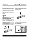
Connect the product supply line to the 1/4” barbed
fitting on thefill module. Adjust the fill system pressure
to deliver product to the hopper at 1.5 to 2.5 oz. (42.5
to 70.9 g) per second. (Approximately 15 to 20 PSIG
[103- 138 kPa] for most products.)
Step 2
Lubricate, assemble, s anitize andprime the dispenser
as outlined in the Assembly section of this manual.
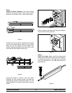
Step 3
Place the fill switch in the “ON” position. Allow the
product to fill the cylinder and the hopper until the mix
level float is satisfied.
Step 4
Place the power switch in the “AUTO” position.
Step 5
To observe the suction pressure, attach refrigeration
gauges to the suction access fitting in the dispenser.
Pressures should read approximately 32 psi. (221
kPa) for non- alcoholic application and 28 psi. (193
kPa) for alcoholic application.
Note: Connection to the condensing unit suction
access can give an improper reading.
Step 6
Allow the dispenser to run until the condensing unit
cycles off.
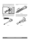
Step 7
If nec essary, adjust viscosity to produce satisfactory
product. Adjustments are m ade by turning the
viscosity adjustment s crew(located onthe front panel)
clockwise for a thicker p roduct or counterclockwise for
a thinner product.