


TW-357 REV E
21
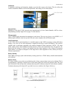
Main Display Screen
The main display screen consists of 4 lines of information.
Line 1: Displays the current status of the control. It indicates if all systems are normal or if any errors have
been detected. Error messages disappear when the error is corrected.
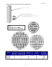
Line 2: Displays the level sensing in the control. If the 7-thermistor or 8-thermistor assembly is being used, the
control will indicate actual liquid level in the freezer. If a 4-thermistor assembly is being used, the control will
indicate LOW if the liquid level is below sensor #2, NORMAL if the liquid level is between sensor #2 and
sensor #3, and HIGH if the liquid level is above sensor #3. In addition, LOW LEVEL ALARM is indicated
when the liquid level is below sensor #1 and HIGH LEVEL ALARM is indicated when liquid level is above
sensor #4.
Line 3: Displays the temperature indicated by thermocouple #1 and #2. If either thermocouple is disabled by
the user through the menu system, it is no longer displayed on the front panel. If both thermocouples are
disabled by the user, line 3 is blank.
Line 4: Used to annotate (or label) the soft-key buttons and to provide information about the valve and the lid
status. In the center of the line, a rotating “baton” provides a visual indication that the control is running and
functioning properly.
The Menu System
Pressing the Soft Key labeled MENU on the front right side of the control will access the menu system.
Choose a menu option by pressing the appropriate number of your menu choice. If more menu choices are
available than will fit on 1 screen (more than 4 choices in this menu section), the left-hand soft-key button will
give the “More” choice Pressing this button will give the user the additional menu choices. A shortcut is
available to get to the proper menu choice by pressing the appropriate number button. The menu choice need
not be visible on the screen to select it.
When the menu is accessed, all control functions cease until the control returns to the main status screen.
Therefore, if a fill is occurring and the menu is accessed, the solenoid valve will close until the menu system is
exited and the control is again displaying the main screen. If the menu system is accessed but not interacted
with for 3 minutes, it will automatically revert to the main screen and all functions will resume.
Please note that the menu system can vary slightly depending on the configuration of the control. Menu
choices will be included or excluded depending on the selected features in the control. This is illustrated in the
menu system when the 4-sensor or the 8-sensor probe assembly is being used. The START FILL and STOP
FILL sensor must be physically set when the 4-sensor probe is in use, so the START FILL level and STOP
FILL level menu items are not displayed. When the control is operated with the 8-sensor assembly, the user
can assign the START FILL and STOP FILL levels with the control key pad without physical intervention to
the sensors in the storage chamber unless you want to change from vapor phase storage to liquid phase
storage. (See Menu Table 1.0 on page 21 of this manual.)