


TW-357 REV E
40
TROUBLESHOOTING
Symptoms
The key to troubleshooting your LABS CryoStorage system is to determine which component in the system is
the source of the problem. Determine if the problem is occurring in any of the following subsystems: Supply
Vessel, Transfer Line, Power Source, Temperature, Level Sensing, Security, Lid Switch, Solenoid Valve,
Control Display, Alarm System, Communications. After determining which sub-system is having the
problem, isolate the problem further by performing sub-system tests. Once the problem is isolated and
defined, it will be easier to solve.
Controller Will Not Turn ON
1. Press POWER button. If display is blank and dark go to next step.
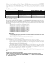
2. Check all connections. Start with jacks at the foot of the controller. Pay special attention to jacks labeled
“POWER”. Wall transformer must be plugged into an outlet providing AC voltage between 100 and 130
to deliver AC voltage 21 to 30 to the back of the freezer.
Indicates High Liquid Level
1. Determine actual liquid level using a dipstick. Select MENU, LEVEL SENSING, TEST LEVEL
SENSORS. An “L” or “G” will indicate individual thermistor status. “L” meaning that the thermistor is
submerged in liquid and “G” indicates that the thermistor is in cold Gas. Determine the pressure, and
remaining liquid level in the supply cylinder (15 to 22 psi). A fill solenoid valve that freezes (or sticks) open
will typically empty the supply cylinder. Replace solenoid valve if it has failed even once.
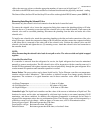
2. Liquid level is sensed by thermistors located in a sensor tube. If the sensor tube is blocked or iced at the top,
the liquid level in the sensor tube may not rise and fall at the same rate as the liquid level in the freezing
chamber. Make sure the sensor tube is not obstructed.
3. The pool of LN2 can become turbulent during a fill. Bubbling and splashing can be amplified by the rack
arrangement. The deeper the pool, the more turbulent the surface of the pool will be during a fill. The
turbulence of the pool surface can splash on the X-High thermistor and cause a false high alarm. Reduce the
splashing.
4. Confirm that sensor assembly is responding to changing liquid level with a dip-test.
• Mark the sensor assembly at top of tube to assure re-assembly.
• Close liquid supply valve at source.
• Remove sensor assembly from sensor tube. DO NOT FORCE. Fill solenoid valve should open and LOW
LEVEL alarm should be activated.
• Select MENU, LEVEL SENSING, TEST LEVEL SENSORS. An “L” or “G” will indicate individual
thermistor status (L = Liquid and G = Gas).
• Dip each thermistor in succession into LN2 Observe the controller display noting that each thermistor
changes from “G” to “L” as each is submerged. Response time may vary.
• Return to the main menu and submerge the START FILL THERMISTOR IN LIQUID. NOTE that the
low level alarm ceases, fill solenoid valve is still open. Control is flashing FILLING.
• Manually press STOP button and note that the fill solenoid valve closes.
• Press FILL button to re-open fill solenoid valve.
• Continue to lower the sensor until the STOP FILL thermistor is immersed in the LN2 . The fill should
stop after a confirming (CHECK) SPLASH GUARD period.